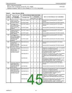
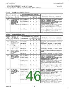
Philips Semiconductors
Preliminary specification
80C51 8-bit microcontroller
8K/256 OTP, 8 channel 10 bit A/D, I2C, PWM,
capture/compare, high I/O, low voltage (2.7V–5.5V), low power
P87C552
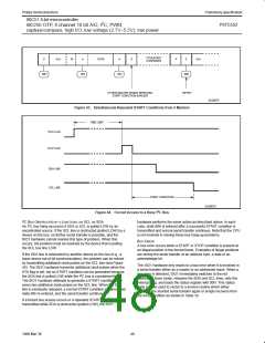
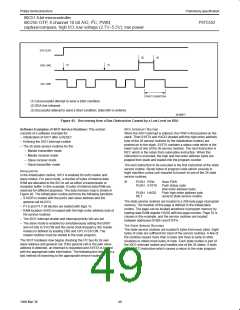
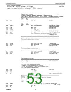
STA FLAG
(2)
(3)
(1)
(1)
SDA LINE
SCL LINE
START CONDITION
(1) Unsuccessful attempt to send a Start condition
(2) SDA line released
(3) Successful attempt to send a Start condition; state 08H is entered
SU00977
Figure 45. Recovering from a Bus Obstruction Caused by a Low Level on SDA
Software Examples of SIO1 Service Routines: This section
SIO1 INTERRUPT ROUTINE
consists of a software example for:
– Initialization of SIO1 after a RESET
When the SIO1 interrupt is entered, the PSW is first pushed on the
stack. Then S1STA and HADD (loaded with the high-order address
byte of the 26 service routines by the initialization routine) are
pushed on to the stack. S1STA contains a status code which is the
lower byte of one of the 26 service routines. The next instruction is
RET, which is the return from subroutine instruction. When this
instruction is executed, the high and low order address bytes are
popped from stack and loaded into the program counter.
– Entering the SIO1 interrupt routine
– The 26 state service routines for the
– Master transmitter mode
– Master receiver mode
– Slave receiver mode
– Slave transmitter mode
The next instruction to be executed is the first instruction of the state
service routine. Seven bytes of program code (which execute in
eight machine cycles) are required to branch to one of the 26 state
service routines.
INITIALIZATION
In the initialization routine, SIO1 is enabled for both master and
slave modes. For each mode, a number of bytes of internal data
RAM are allocated to the SIO to act as either a transmission or
reception buffer. In this example, 8 bytes of internal data RAM are
reserved for different purposes. The data memory map is shown in
Figure 46. The initialization routine performs the following functions:
– S1ADR is loaded with the part’s own slave address and the
general call bit (GC)
SI
PUSH PSW
Save PSW
PUSH S1STA
Push status code
(low order address byte)
Push high order address byte
Jump to state service routine
PUSH HADD
RET
The state service routines are located in a 256-byte page of program
memory. The location of this page is defined in the initialization
routine. The page can be located anywhere in program memory by
loading data RAM register HADD with the page number. Page 01 is
chosen in this example, and the service routines are located
between addresses 0100H and 01FFH.
– P1.6 and P1.7 bit latches are loaded with logic 1s
– RAM location HADD is loaded with the high-order address byte of
the service routines
– The SIO1 interrupt enable and interrupt priority bits are set
– The slave mode is enabled by simultaneously setting the ENS1
and AA bits in S1CON and the serial clock frequency (for master
modes) is defined by loading CR0 and CR1 in S1CON. The
master routines must be started in the main program.
THE STATE SERVICE ROUTINES
The state service routines are located 8 bytes from each other. Eight
bytes of code are sufficient for most of the service routines. A few of
the routines require more than 8 bytes and have to jump to other
locations to obtain more bytes of code. Each state routine is part of
the SIO1 interrupt routine and handles one of the 26 states. It ends
with a RETI instruction which causes a return to the main program.
2
The SIO1 hardware now begins checking the I C bus for its own
slave address and general call. If the general call or the own slave
address is detected, an interrupt is requested and S1STA is loaded
with the appropriate state information. The following text describes a
fast method of branching to the appropriate service routine.
49
1999 Mar 30

 NXP [ NXP ]