NTAG213F/216F
NXP Semiconductors
NFC Forum T2T IC with 144/888 bytes user memory and field detection
COMPATIBILITY_WRITE command, and the contents of the lock bytes are bit-wise
OR’ed and the result then becomes the new content of the lock bytes. This process is
irreversible. If a bit is set to logic 1, it cannot be changed back to logic 0.
The contents of bytes 0 and 1 of page 02h are unaffected by the corresponding data bytes
of the WRITE or COMPATIBILITY_WRITE command.
The default value of the static lock bytes is 00 00h.
Any write operation to the static lock bytes is tearing-proof.
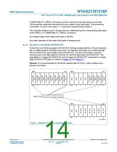
8.5.3 Dynamic Lock Bytes (NTAG21xF)
To lock the User Memory pages of NTAG21xF starting at page address 10h and onwards,
the so called dynamic lock bytes are used. The dynamic lock bytes are located at page
28h for NTAG213F and at page E2h for NTAG216F. The three lock bytes cover the
memory area of 96 data bytes for NTAG213F and 830 data bytes for NTAG216F. The
granularity is 2 pages for NTAG213F and 16 pages for NTAG216F compared to a single
page for the first 48 bytes as shown in Figure 10 and Figure 11.
Remark: It is recommended to set all bits marked with RFUI to 0, when writing to the
dynamic lock bytes.
MSB
LSB
MSB
LSB
bit 7
6
5
4
3
2
1
0
bit 7
6
5
4
3
2
1
0
1
3
page 40 (28h)
0
2
MSB
LSB
bit 7
6
5
4
3
2
1
0
aaa-008090
Fig 10. NTAG213F Dynamic lock bytes 0, 1 and 2
NTAG213F_216F
All information provided in this document is subject to legal disclaimers.
© NXP B.V. 2013. All rights reserved.
Product data sheet
COMPANY PUBLIC
Rev. 3.1 — 28 August 2013
262231
14 of 56

 NXP [ NXP ]