Philips Semiconductors
Product specification
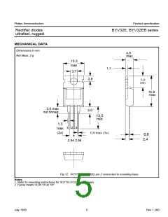
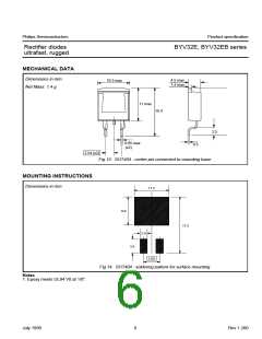
Rectifier diodes
ultrafast, rugged
BYV32E, BYV32EB series
dI
0.5A
IF
I
F
F
dt
t
0A
rr
time
I
= 0.25A
rec
IR
Q
100%
10%
s
trr2
I
I
R
rrm
I = 1A
R
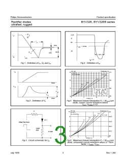
Fig.1. Definition of trr1, Qs and Irrm
Fig.4. Definition of trr2
Tmb(max) / C
D = 1.0
PF / W
Vo = 0.7 V
BYV32
I
15
114
F
F
Rs = 0.0183 Ohms
0.5
126
10
5
0.2
time
0.1
V
138
150
t
p
t
p
I
D =
T
V
fr
t
T
V
F
0
0
5
10
15
time
IF(AV) / A
Fig.2. Definition of Vfr
Fig.5. Maximum forward dissipation PF = f(IF(AV)) per
diode; square current waveform where
IF(AV) =IF(RMS) x √D.
PF / W
Vo = 0.7 V
BYV32
2.8
Tmb(max) / C
a = 1.57
R
10
8
126
1.9
Rs = 0.0183 Ohms
2.2
130.8
D.U.T.
4
6
135.6
140.4
145.2
150
Voltage Pulse Source
4
Current
shunt
2
to ’scope
0
0
2
4
6
8
10
IF(AV) / A
Fig.3. Circuit schematic for trr2
Fig.6. Maximum forward dissipation PF = f(IF(AV)) per
diode; sinusoidal current waveform where a = form
factor = IF(RMS) / IF(AV)
.
July 1998
3
Rev 1.200

 NXP [ NXP ]