Philips Semiconductors
Product specification
Rectifier diodes
ultrafast, rugged
BYV32E, BYV32EB series
ESD LIMITING VALUE
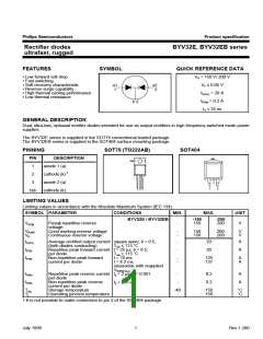
SYMBOL PARAMETER
CONDITIONS
MIN.
MAX.
UNIT
VC
Electrostatic discharge
capacitor voltage
Human body model;
C = 250 pF; R = 1.5 kΩ
-
8
kV
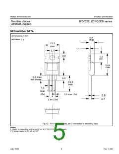
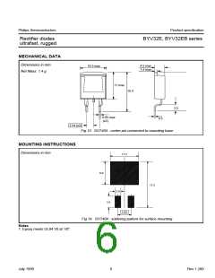
THERMAL RESISTANCES
SYMBOL PARAMETER
CONDITIONS
MIN. TYP. MAX. UNIT
Rth j-mb
Rth j-a
Thermal resistance junction per diode
to mounting base both diodes
Thermal resistance junction SOT78 package, in free air
to ambient SOT404 and SOT428 packages, pcb
mounted, minimum footprint, FR4 board
-
-
-
-
-
2.4
1.6
-
K/W
K/W
K/W
K/W
-
60
50
-
ELECTRICAL CHARACTERISTICS
characteristics are per diode at Tj = 25 ˚C unless otherwise stated
SYMBOL PARAMETER
CONDITIONS
MIN. TYP. MAX. UNIT
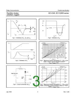
VF
Forward voltage
IF = 8 A; Tj = 150˚C
-
-
-
-
-
-
0.72
1.00
0.2
6
0.85
1.15
0.6
V
V
mA
µA
nC
ns
IF = 20 A
IR
Reverse current
VR = VRWM; Tj = 100 ˚C
VR = VRWM
30
Qs
trr1
Reverse recovery charge
Reverse recovery time
IF = 2 A; VR ≥ 30 V; -dIF/dt = 20 A/µs
IF = 1 A; VR ≥ 30 V;
8
12.5
25
20
-dIF/dt = 100 A/µs
trr2
Vfr
Reverse recovery time
Forward recovery voltage
IF = 0.5 A to IR = 1 A; Irec = 0.25 A
IF = 1 A; dIF/dt = 10 A/µs
-
-
10
1
20
-
ns
V
July 1998
2
Rev 1.200

 NXP [ NXP ]