Philips Semiconductors
Product specification
Thyristors
logic level
BT149 series
Tc(max) / C
Ptot / W
0.8
BT169
2.2
ITSM / A
BT169
77
10
8
conduction form
a = 1.57
I
angle
factor
a
TSM
time
I
T
0.7
0.6
0.5
0.4
0.3
0.2
0.1
0
83
degrees
1.9
30
60
90
120
180
4
2.8
2.2
1.9
1.57
T
89
Tj initial = 25 C max
95
2.8
6
101
107
4
4
113
119
125
2
0
0
0.1
0.2
0.3
0.4
0.5
0.6
0.7
1
10
100
1000
IF(AV) / A
Number of half cycles at 50Hz
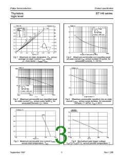
Fig.1. Maximum on-state dissipation, Ptot, versus
average on-state current, IT(AV), where
Fig.4. Maximum permissible non-repetitive peak
on-state current ITSM, versus number of cycles, for
sinusoidal currents, f = 50 Hz.
a = form factor = IT(RMS)/ IT(AV)
.
BT169
ITSM / A
BT169
IT(RMS) / A
1000
100
10
2
1.5
1
I
TSM
time
I
T
0.5
0
T
Tj initial = 25 C max
1
10ms
10us
100us
1ms
0.01
0.1
1
10
T / s
surge duration / s
Fig.2. Maximum permissible non-repetitive peak
on-state current ITSM, versus pulse width tp, for
sinusoidal currents, tp ≤ 10ms.
Fig.5. Maximum permissible repetitive rms on-state
current IT(RMS), versus surge duration, for sinusoidal
currents, f = 50 Hz; Tlead ≤ 83˚C.
IT(RMS) / A
BT169
VGT(Tj)
1
BT151
VGT(25 C)
1.6
1.4
1.2
1
83 C
0.8
0.6
0.4
0.2
0
0.8
0.6
0.4
-50
0
50
Tlead / C
100
150
-50
0
50
100
150
Tj / C
Fig.3. Maximum permissible rms current IT(RMS)
versus lead temperature, Tlead
,
Fig.6. Normalised gate trigger voltage
VGT(Tj)/ VGT(25˚C), versus junction temperature Tj.
.
September 1997
3
Rev 1.200

 NXP [ NXP ]