74LVC14A
Philips Semiconductors
Hex inverting Schmitt trigger with 5 V tolerant input
13. Waveforms
V
I
V
M
nA input
GND
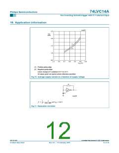
t
t
PHL
PLH
V
OH
V
nY output
M
V
OL
mna344
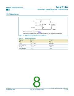
Measurement points are given in Table 9.
Logic levels: VOL and VOH are typical output voltage drop that occur with the output load.
Fig 6. Propagation delay input (nA) to output (nY)
Table 9:
Supply
VCC
Measurement points
Input
VM
Output
VM
1.2 V
0.5 × VCC
0.5 × VCC
0.5 × VCC
1.5 V
2.3 V to 2.7 V
2.7 V
0.5 × VCC
1.5 V
3.0 V to 3.6 V
1.5 V
1.5 V
9397 750 14591
© Koninklijke Philips Electronics N.V. 2005. All rights reserved.
Product data sheet
Rev. 04 — 15 February 2005
8 of 19

 NXP [ NXP ]