Philips Semiconductors
Product specification
Octal D-type flip-flop with reset;
positive-edge trigger
74HC/HCT273
DC CHARACTERISTICS FOR 74HCT
For the DC characteristics see “74HC/HCT/HCU/HCMOS Logic Family Specifications”.
Output capability: standard
ICC category: MSI
Note to HCT types
The value of additional quiescent supply current (∆ICC) for a unit load of 1 is given in the family specifications.
To determine ∆ICC per input, multiply this value by the unit load coefficient shown in the table below.
INPUT
UNIT LOAD COEFFICIENT
MR
CP
Dn
1.00
1.75
0.15
AC CHARACTERISTICS FOR 74HCT
GND = 0 V; tr = tf = 6 ns; CL = 50 pF
Tamb (°C)
TEST CONDITIONS
74HCT
SYMBOL PARAMETER
UNIT
WAVEFORMS
VCC
(V)
+25
−40 to +85 −40 to +125
min. typ. max. min. max. min. max.
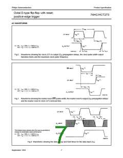
tPHL/ tPLH propagation delay
CP to Qn
16
23
7
30
34
15
38
43
19
45
51
22
ns
ns
ns
ns
ns
ns
ns
ns
4.5 Fig.6
4.5 Fig.7
4.5 Fig.6
4.5 Fig.6
4.5 Fig.7
4.5 Fig.7
4.5 Fig.8
4.5 Fig.8
tPHL
propagation delay
MR to Qn
t
THL/ tTLH output transition time
tW
tW
trem
tsu
th
clock pulse width
HIGH or LOW
16
9
20
20
13
15
3
24
24
15
18
3
master reset pulse width 16
LOW
8
removal time
MR to CP
10
12
3
−2
5
set-up time
Dn to CP
hold time
Dn to CP
−4
56
fmax
maximum clock pulse
frequency
30
24
20
MHz 4.5 Fig.6
September 1993
6

 NXP [ NXP ]