Philips Semiconductors
Product specification
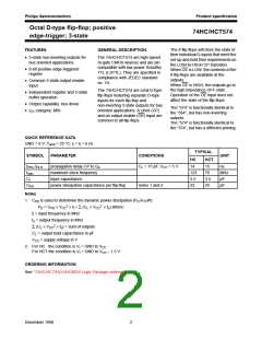
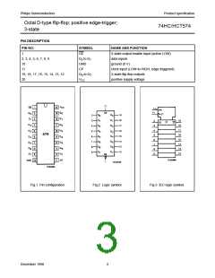
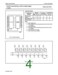
Octal D-type flip-flop; positive edge-trigger;
3-state
74HC/HCT574
DC CHARACTERISTICS FOR 74HCT
For the DC characteristics see “74HC/HCT/HCU/HCMOS Logic Family Specifications”.
Output capability: bus driver
ICC category: MSI
Note to HCT types
The value of additional quiescent supply current (∆ICC) for a unit load of 1 is given in the family specifications.
To determine ∆ICC per input, multiply this value by the unit load coefficient shown in the table below.
INPUT
UNIT LOAD COEFFICIENT
Dn
0.5
OE
CP
1.25
1.5
AC CHARACTERISTICS FOR 74HCT
GND = 0 V; tr = tf = 6 ns; CL = 50 pF
Tamb (°C)
TEST CONDITIONS
74HCT
SYMBOL PARAMETER
UNIT
VCC
+25
−40 to +85 −40 to +125
WAVEFORMS
(V)
min. typ. max. min. max. min. max.
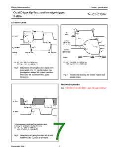
tPHL/ tPLH propagation delay
CP to Qn
18
19
16
5
33
33
28
12
41
41
35
15
50
50
42
18
ns
ns
ns
ns
ns
ns
ns
4.5 Fig.6
4.5 Fig.7
4.5 Fig.7
4.5 Fig.6
4.5 Fig.6
4.5 Fig.8
4.5 Fig.8
tPZH/ tPZL 3-state output enable
time OE to Qn
t
PHZ/ tPLZ 3-state output disable
time OE to Qn
tTHL/ tTLH output transition time
tW
clock pulse width
HIGH or LOW
16
12
5
7
20
15
5
24
18
5
tsu
th
set-up time
Dn to CP
3
hold time
Dn to CP
−1
69
fmax
maximum clock pulse
frequency
30
24
20
MHz 4.5 Fig.6
December 1990
6

 NXP [ NXP ]