Philips Semiconductors
Product specification
Octal D-type flip-flop; positive edge-trigger;
3-state
74HC/HCT574
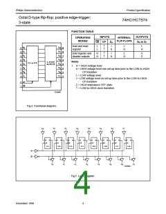
FUNCTION TABLE
INPUTS
OE CP
OUTPUTS
OPERATING
MODES
INTERNAL
FLIP-FLOPS
Dn
Q0 to Q7
load and read
register
L
L
↑
↑
l
h
L
H
L
H
load register and
disable outputs
H
H
↑
↑
l
h
L
H
Z
Z
Notes
1. H = HIGH voltage level
h = HIGH voltage level one set-up time prior to the LOW-to-HIGH
CP transition
L = LOW voltage level
l = LOW voltage level on set-up time prior to the LOW-to-HIGH
CP transition
Z = HIGH impedance OFF-state
↑ = LOW-to-HIGH clock transition
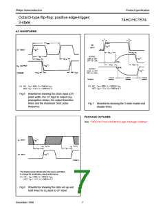
Fig.4 Functional diagram.
Fig.5 Logic diagram.
December 1990
4

 NXP [ NXP ]