Philips Semiconductors
Product specification
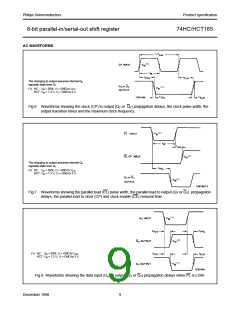
8-bit parallel-in/serial-out shift register
74HC/HCT165
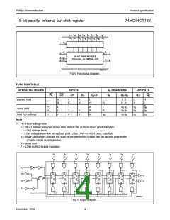
Fig.4 Functional diagram.
FUNCTION TABLE
OPERATING MODES
INPUTS
CP
Qn REGISTERS
OUTPUTS
Q7 Q7
PL
CE
DS
D0-D7
Q0
Q1-Q6
parallel load
serial shift
L
L
X
X
X
X
X
X
L
H
L
H
L - L
H - H
L
H
H
L
H
H
L
L
↑
↑
l
h
X
X
L
H
q0-q5
q0-q5
q6
q6
q6
q6
hold “do nothing”
H
H
X
X
X
q0
q1-q6
q7
q7
Note
1. H = HIGH voltage level
h = HIGH voltage level one set-up time prior to the LOW-to-HIGH clock transition
L = LOW voltage level
I = LOW voltage level one set-up time prior to the LOW-to-HIGH clock transition
q = lower case letters indicate the state of the referenced output one set-up time prior to the
LOW-to-HIGH clock transition
X = don’t care
↑ = LOW-to-HIGH clock transition
Fig.5 Logic diagram.
December 1990
4

 NXP [ NXP ]