Philips Semiconductors
Product specification
8-bit serial-in/parallel-out shift register
74HC/HCT164
AC WAVEFORMS
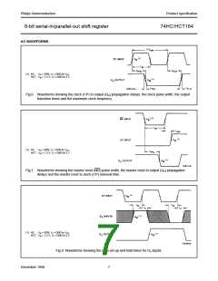
(1) HC : VM = 50%; VI = GND to VCC
.
HCT : VM = 1.3 V; VI = GND to 3 V.
Fig.6 Waveforms showing the clock (CP) to output (Qn) propagation delays, the clock pulse width, the output
transition times and the maximum clock frequency.
(1) HC : VM = 50%; VI = GND to VCC
.
HCT : VM = 1.3 V; VI = GND to 3 V.
Fig.7 Waveforms showing the master reset (MR) pulse width, the master reset to output (Qn) propagation
delays and the master reset to clock (CP) removal time.
(1) HC : VM = 50%; VI = GND to VCC
.
HCT : VM = 1.3 V; VI = GND to 3 V.
Fig.8 Waveforms showing the data set-up and hold times for Dn inputs.
December 1990
7

 NXP [ NXP ]