Philips Semiconductors
Product specification
8-bit serial-in/parallel-out shift register
74HC/HCT164
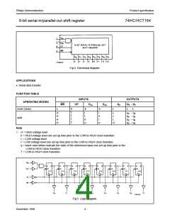
Fig.4 Functional diagram.
APPLICATIONS
• Serial data transfer
FUNCTION TABLE
INPUTS
OUTPUTS
OPERATING MODES
MR
CP
Dsa
Dsb
Q0
Q1 − Q7
reset (clear)
shift
L
X
X
X
L
L − L
H
H
H
H
↑
↑
↑
↑
l
l
h
h
l
h
l
L
L
L
H
q0 − q6
q0 − q6
q0 − q6
q0 − q6
h
Note
1. H = HIGH voltage level
h = HIGH voltage level one set-up time prior to the LOW-to-HIGH clock transition
L = LOW voltage level
I = LOW voltage level one set-up time prior to the LOW-to-HIGH clock transition
q = lower case letters indicate the state of the referenced input one set-up time prior to the
LOW-to-HIGH clock transition
↑ = LOW-to-HIGH clock transition
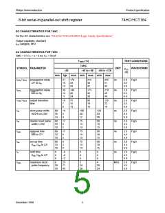
Fig.5 Logic diagram.
December 1990
4

 NXP [ NXP ]