Philips Semiconductors
Product specification
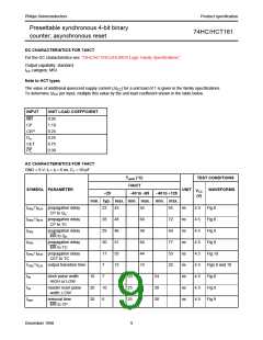
Presettable synchronous 4-bit binary
counter; asynchronous reset
74HC/HCT161
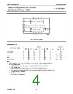
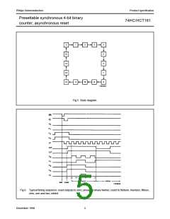
Fig.4 Functional diagram.
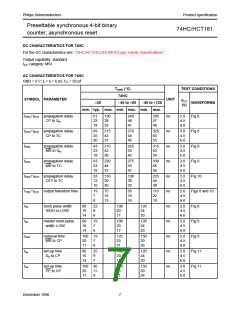
FUNCTION TABLE
OPERATING MODE
INPUTS
CEP CET
OUTPUTS
MR
CP
PE
Dn
Qn
TC
reset (clear)
parallel load
L
X
X
X
X
X
L
L
H
H
↑
↑
X
X
X
X
I
I
I
h
L
H
L
(1)
(1)
(1)
L
count
H
↑
h
h
h
X
count
hold
(do nothing)
H
H
X
X
I
X
X
I
h
h
X
X
qn
qn
Note
1. The TC output is HIGH when CET is HIGH and the counter is at terminal count (HHHH).
H = HIGH voltage level
h = HIGH voltage level one set-up time prior to the LOW-to-HIGH CP transition
L = LOW voltage level
I = LOW voltage level one set-up time prior to the LOW-to-HIGH CP transition
q = lower case letters indicate the state of the referenced output one set-up time prior to the
LOW-to-HIGH CP transition
X = don’t care
↑ = LOW-to-HIGH CP transition
December 1990
4

 NXP [ NXP ]