Philips Semiconductors
Product specification
Hex inverting Schmitt trigger
74HC14; 74HCT14
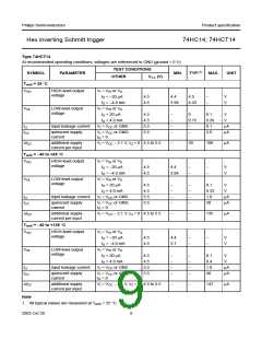
Type 74HCT
GND = 0 V; tr = tf = 6 ns; CL = 50 pF
TEST CONDITIONS
WAVEFORMS CC (V)
SYMBOL
amb = 25 °C; note 1
PARAMETER
MIN.
TYP.
MAX.
UNIT
V
T
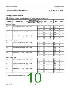
tPHL/tPLH
THL/tTLH
propagation delay nA to nY
output transition time
see Fig.9
4.5
4.5
−
−
20
34
ns
t
see Fig.9
7
15
ns
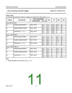
Tamb = −40 to +85 °C
tPHL/tPLH propagation delay nA to nY
tTHL/tTLH output transition time
Tamb = −40 to +125 °C
tPHL/tPLH propagation delay nA to nY
THL/tTLH output transition time
see Fig.9
see Fig.9
4.5
4.5
43
19
−
−
−
−
ns
ns
see Fig.9
see Fig.9
4.5
4.5
−
−
−
−
51
22
ns
ns
t
Note
1. All typical values are measured at Tamb = 25 °C.
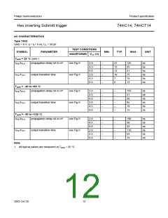
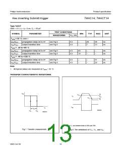
TRANSFER CHARACTERISTIC WAVEFORMS
V
O
handbook, halfpage
V
T+
V
I
V
H
V
T−
V
O
V
I
V
H
MNA845
V
V
T+
T−
MNA844
VT+ and VT− are between limits of 20% and 70%.
Fig.7 Transfer characteristic.
Fig.8 The definitions of VT+, VT− and VH.
2003 Oct 30
13

 NXP [ NXP ]