Philips Semiconductors
Product specification
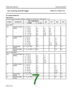
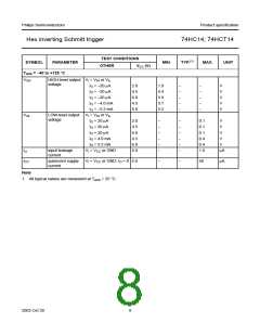
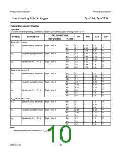
Hex inverting Schmitt trigger
74HC14; 74HCT14
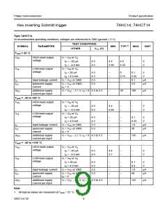
Family 74HCT
At recommended operating conditions: voltages are referenced to GND (ground = 0 V)
TEST CONDITIONS
SYMBOL
PARAMETER
MIN.
TYP.
MAX.
UNIT
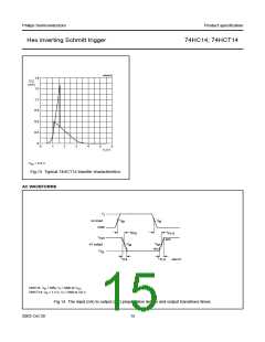
WAVEFORMS
VCC (V)
Tamb = 25 °C; note 1
VT+
VT−
VH
positive-going threshold
negative-going threshold
hysteresis (VT+ − VT−)
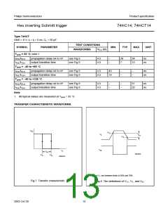
Figs 7 and 8
4.5
5.5
4.5
5.5
4.5
5.5
1.2
1.41
1.9
V
1.4
0.5
0.6
0.4
0.4
1.59
0.85
0.99
0.56
0.60
2.1
1.2
1.4
−
V
V
V
V
V
Figs 7 and 8
Figs 7 and 8
−
Tamb = −40 to +85 °C
VT+
positive-going threshold
negative-going threshold
hysteresis (VT+ − VT−)
Figs 7 and 8
Figs 7 and 8
Figs 7 and 8
4.5
5.5
4.5
5.5
4.5
5.5
1.2
1.4
0.5
0.6
0.4
0.4
−
−
−
−
−
−
1.9
2.1
1.2
1.4
−
V
V
V
V
V
V
VT−
VH
−
Tamb = −40 to +125 °C
VT+
VT−
VH
positive-going threshold
Figs 7 and 8
Figs 7 and 8
Figs 7 and 8
4.5
5.5
4.5
5.5
4.5
5.5
1.2
1.4
0.5
0.6
0.4
0.4
−
−
−
−
−
−
1.9
2.1
1.2
1.4
−
V
V
V
V
V
V
negative-going threshold
hysteresis (VT+ − VT−)
−
Note
1. All typical values are measured at Tamb = 25 °C.
2003 Oct 30
11

 NXP [ NXP ]