Philips Semiconductors
Product specification
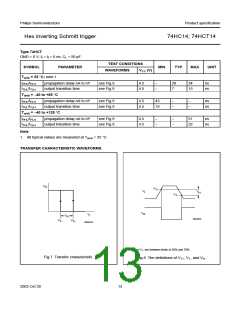
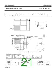
Hex inverting Schmitt trigger
74HC14; 74HCT14
APPLICATION INFORMATION
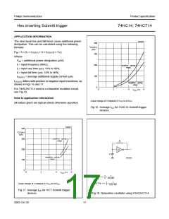
The slow input rise and fall times cause additional power
dissipation. This can be calculated using the following
formula:
MNA852
400
handbook, halfpage
I
CC(AV)
(µA)
Pad = fi × (tr × ICC(AV) + tf × ICC(AV)) × VCC
.
300
Where:
Pad = additional power dissipation (µW);
fi = input frequency (MHz);
200
100
positive - going
edge
tr = input rise time (µs); 10% to 90%;
tf = input fall time (µs); 10% to 90%;
ICC(AV) = average additional supply current (µA).
ICC(AV) differs with positive or negative input transitions, as
shown in Figs 16 and 17.
negative - going
edge
0
0
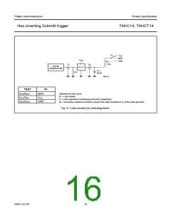
For 74HC/HCT14 used in a relaxation oscillator circuit,
see Fig.18.
2
4
6
V
(V)
CC
Note to application information
Linear change of VI between 0.1VCC to 0.9VCC
All values given are typical unless otherwise specified.
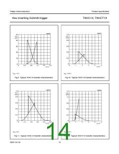
Fig.16 Average ICC for 74HC14 Schmitt trigger
devices.
MNA853
400
handbook, halfpage
I
CC(AV)
(µA)
positive - going
edggde
300
200
100
0
R
handbook, halfpage
C
negative - going
edggde
MNA854
0
2
4
6
V
(V)
CC
1
T
1
74HC14 : f =
≈
--- ------------------
0.8 RC
1
T
1
74HCT14 : f =
≈
--- ---------------------
Linear change of VI between 0.1VCC to 0.9VCC
.
0.67 RC
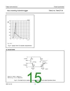
Fig.17 Average ICC for HCT Schmitt trigger
devices.
Fig.18 Relaxation oscillator using 74HC/HCT14.
2003 Oct 30
17

 NXP [ NXP ]