Philips Semiconductors
Product specification
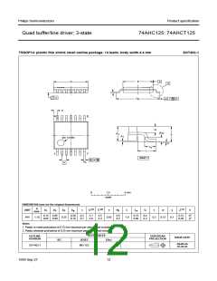
Quad buffer/line driver; 3-state
74AHC125; 74AHCT125
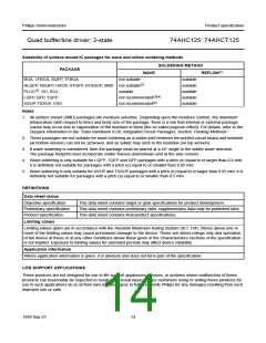
Suitability of surface mount IC packages for wave and reflow soldering methods
SOLDERING METHOD
REFLOW(1)
PACKAGE
WAVE
BGA, LFBGA, SQFP, TFBGA
HLQFP, HSQFP, HSOP, HTQFP, HTSSOP, SMS not suitable(2)
PLCC(3), SO, SOJ
LQFP, QFP, TQFP
SSOP, TSSOP, VSO
not suitable
suitable
suitable
suitable
suitable
suitable
suitable
not recommended(3)(4)
not recommended(5)
Notes
1. All surface mount (SMD) packages are moisture sensitive. Depending upon the moisture content, the maximum
temperature (with respect to time) and body size of the package, there is a risk that internal or external package
cracks may occur due to vaporization of the moisture in them (the so called popcorn effect). For details, refer to the
Drypack information in the “Data Handbook IC26; Integrated Circuit Packages; Section: Packing Methods”.
2. These packages are not suitable for wave soldering as a solder joint between the printed-circuit board and heatsink
(at bottom version) can not be achieved, and as solder may stick to the heatsink (on top version).
3. If wave soldering is considered, then the package must be placed at a 45° angle to the solder wave direction.
The package footprint must incorporate solder thieves downstream and at the side corners.
4. Wave soldering is only suitable for LQFP, TQFP and QFP packages with a pitch (e) equal to or larger than 0.8 mm;
it is definitely not suitable for packages with a pitch (e) equal to or smaller than 0.65 mm.
5. Wave soldering is only suitable for SSOP and TSSOP packages with a pitch (e) equal to or larger than 0.65 mm; it is
definitely not suitable for packages with a pitch (e) equal to or smaller than 0.5 mm.
DEFINITIONS
Data sheet status
Objective specification
Preliminary specification
Product specification
This data sheet contains target or goal specifications for product development.
This data sheet contains preliminary data; supplementary data may be published later.
This data sheet contains final product specifications.
Limiting values
Limiting values given are in accordance with the Absolute Maximum Rating System (IEC 134). Stress above one or
more of the limiting values may cause permanent damage to the device. These are stress ratings only and operation
of the device at these or at any other conditions above those given in the Characteristics sections of the specification
is not implied. Exposure to limiting values for extended periods may affect device reliability.
Application information
Where application information is given, it is advisory and does not form part of the specification.
LIFE SUPPORT APPLICATIONS
These products are not designed for use in life support appliances, devices, or systems where malfunction of these
products can reasonably be expected to result in personal injury. Philips customers using or selling these products for
use in such applications do so at their own risk and agree to fully indemnify Philips for any damages resulting from such
improper use or sale.
1999 Sep 27
14

 NXP [ NXP ]