OXCB950
OXFORD SEMICONDUCTOR LTD.
7.10 Baud Rate Generation
7.10.1 General Operation
7.10.2 Clock Prescaler Register ‘CPR’
The UART contains a programmable baud rate generator
that is capable of taking any clock input from 1.8432MHz to
60MHz and dividing it by any 16-bit divisor number from 1
to 65535 written into the DLM (MSB) and DLL (LSB)
registers. In addition to this, a clock prescaler register is
provided which can further divide the clock by values in the
range 1.0 to 31.875 in steps of 0.125. Also, a further
feature is the Times Clock Register ‘TCR’ which allows the
sampling clock to be set to any value between 4 and 16.
The CPR register is located at offset 0x01 of the ICR
The prescaler divides the system clock by any value in the
range of 1 to “31 7/8” in steps of 1/8. The divisor takes the
form “M+N/8”, where M is the 5 bit value defined in
CPR[7:3] and N is the 3 bit value defined in CPR[2:0].
The prescaler is by-passed and a prescaler value of ‘1’ is
selected by default when MCR[7] = 0.
These clock options allow for highly flexible baud rate
generation capabilities from almost any input clock
frequency (up to 60MHz). The actual transmitter and
receiver baud rate is calculated as follows:
Note that since access to MCR[7] is restricted to Enhanced
mode only, EFR[4] should first be set and then MCR[7] set
or cleared as required.
For higher baud rates use a higher frequency clock, e.g.
14.7456MHz, 18.432MHz, 32MHz, 40MHz or 60.0MHz.
The flexible prescaler allows system designers to use
clocks that are not integer multiples of popular baud rates;
when using a non-standard clock frequency, compatibility
with existing 16C550 software drivers may be maintained
with a minor software patch to program the on-board
prescaler to divide the high frequency clock down to
1.8432MHz.
InputClock
SC * Divisor * prescaler
BaudRate =
Where:
SC
= Sample clock values defined in TCR[3:0]
Divisor = DLL + ( 256 x DLM )
Prescaler = 1 when MCR[7] = ‘0’ else:
= M + ( N / 8 ) where:
M
N
= CPR[7:3] (Integer part – 1 to 31)
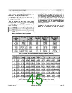
Table 21 on the following page gives the prescaler values
required to operate the UARTs at compatible baud rates
with various different crystal frequencies. Also given is the
maximum available baud rates in TCR = 16 and TCR = 4
modes with CPR = 1.
= CPR[2:0] (Fractional part – 0.000 to 0.875 )
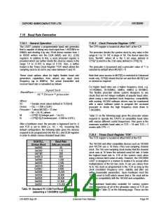
After a hardware reset, the precaler is bypassed (set to 1)
and TCR is set to 0x00 (i.e. SC = 16). Assuming this
default configuration, the following table gives the divisors
required to be programmed into the DLL and DLM registers
in order to obtain various standard baud rates:
7.10.3 Times Clock Register ‘TCR’
The TCR register is located at offset 0x02 of the ICR
DLM:DLL
Divisor Word
0x0900
Baud Rate
(bits per second)
50
The 16C550 and other compatible devices such as 16C650
and 16C750 use a 16 times (16x) over-sampling channel
clock. The 16x over-sampling clock means that the channel
clock runs at 16 times the selected serial bit rate. It limits
the highest baud rate to 1/16 of the system clock when
using a divisor latch value of unity. However, the OXCB950
UART is designed in a manner to enable it to accept other
multiplications of the bit rate clock. It can use values from
4x to 16x clock as programmed in the TCR as long as the
clock (oscillator) frequency error, stability and jitter are
within reasonable parameters. Upon hardware reset the
TCR is reset to 0x00 which means that a 16x clock will be
used, for compatibility with the 16C550 and compatibles.
0x0300
110
0x0180
300
0x00C0
0x0060
600
1,200
0x0030
2,400
0x0018
4,800
0x000C
0x0006
9,600
19,200
28,800
38,400
57,600
115,200
0x0004
0x0003
0x0002
The maximum baud-rates available for various system
clock frequencies at all of the allowable values of TCR are
indicated in Table 22 on the following page. These are the
0x0001
Table 19: Standard PC COM Port Baud Rate Divisors
(assuming a 1.8432MHz crystal)
DS-0033 Sep 05
External-Free Release
Page 44

 OXFORD [ OXFORD SEMICONDUCTOR ]