OXCB950
OXFORD SEMICONDUCTOR LTD.
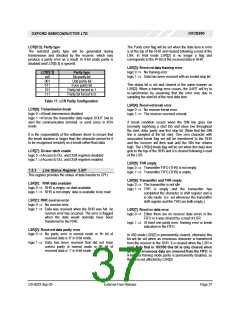
LCR[5:3]: Parity type
The Parity error flag will be set when the data item in error
is at the top of the RHR and cleared following a read of the
LSR. In 9-bit mode LSR[2] is no longer a flag and
The selected parity type will be generated during
transmission and checked by the receiver, which may
produce a parity error as a result. In 9-bit mode parity is
disabled and LCR[5:3] is ignored.
th
corresponds to the 9 bit of the received data in RHR.
LSR[3]: Received data framing error
logic 0 ⇒ No framing error.
LCR[5:3]
xx0
Parity type
No parity bit
logic 1 ⇒ Data has been received with an invalid stop bit.
001
Odd parity bit
This status bit is set and cleared in the same manner as
LSR[2]. When a framing error occurs, the UART will try to
re-synchronise by assuming that the error was due to
sampling the start bit of the next data item.
011
Even parity bit
101
Parity bit forced to 1
Parity bit forced to 0
111
Table 17: LCR Parity Configuration
LSR[4]: Received break error
LCR[6]: Transmission break
logic 0 ⇒ No receiver break error.
logic 1 ⇒ The receiver received a break.
logic 0 ⇒Break transmission disabled.
logic 1 ⇒Forces the transmitter data output SOUT low to
alert the communication terminal, or send zeros in IrDA
mode.
A break condition occurs when the SIN line goes low
(normally signifying a start bit) and stays low throughout
the start, data, parity and first stop bit. (Note that the SIN
line is sampled at the bit rate). One zero character with
associated break flag set will be transferred to the RHR
and the receiver will then wait until the SIN line returns
high. The LSR[4] break flag will be set when this data item
gets to the top of the RHR and it is cleared following a read
of the LSR.
It is the responsibility of the software driver to ensure that
the break duration is longer than the character period for it
to be recognised remotely as a break rather than data.
LCR[7]: Divisor latch enable
logic 0 ⇒Access to DLL and DLM registers disabled.
logic 1 ⇒Access to DLL and DLM registers enabled.
LSR[5]: THR empty
logic 0 ⇒ Transmitter FIFO (THR) is not empty.
logic 1 ⇒ Transmitter FIFO (THR) is empty.
7.5.3 Line Status Register ‘LSR’
This register provides the status of data transfer to CPU.
LSR[6]: Transmitter and THR empty
LSR[0]: RHR data available
logic 0 ⇒ The transmitter is not idle
logic 0 ⇒ RHR is empty: no data available
logic 1 ⇒ RHR is not empty: data is available to be read.
logic 1 ⇒ THR is empty and the transmitter has
completed the character in shift register and is
in idle mode. (I.e. set whenever the transmitter
shift register and the THR are both empty.)
LSR[1]: RHR overrun error
logic 0 ⇒ No overrun error.
logic 1 ⇒ Data was received when the RHR was full. An
overrun error has occurred. The error is flagged
when the data would normally have been
transferred to the RHR.
LSR[7]: Receiver data error
logic 0 ⇒ Either there are no receiver data errors in the
FIFO or it was cleared by a read of LSR.
logic 1 ⇒ At least one parity error, framing error or break
indication in the FIFO.
LSR[2]: Received data parity error
th
logic 0 ⇒ No parity error in normal mode or 9 bit of
In 450 mode LSR[7] is permanently cleared, otherwise this
bit will be set when an erroneous character is transferred
from the receiver to the RHR. It is cleared when the LSR is
read. Note that in 16C550 this bit is only cleared when
all of the erroneous data are removed from the FIFO. In
9-bit data framing mode parity is permanently disabled, so
this bit is not affected by LSR[2].
received data is ‘0’ in 9-bit mode.
logic 1 ⇒ Data has been received that did not have
th
correct parity in normal mode or 9 bit of
received data is ‘1’ in 9-bit mode.
DS-0033 Sep 05
External-Free Release
Page 37

 OXFORD [ OXFORD SEMICONDUCTOR ]