NCV7694
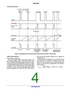
Timing Characteristics
e.g.: 45 Hz = 22 .2 ms period
Double frequency pulse
Typical pulse
Too long pulse
Typical pulse
Short pulse
FLASH
ET threhsold
Exposure Time
Counter
t
ETL
t
FRL
FR threshold
Frame Rate
Counter
LED output
Rest of the pulse
Typical pulse
Short pulse
Driver is activated with
next rising edge of
FLASH pulse
Second pulse is cut off
because “FR” counter is
not reach the threshold
is cut−OFF because “ET”
counter exceed the
threshold
Figure 4. Simplified Internal Timing Characteristic of the Internal ETL, FRL Counter
Safety Feature Behavior
The period of the internals counters can be adjusted by
external resistors.
External Resistor Approach
Total tolerance of the maximum T or maximum Frame
ON
The resistor (RETL, RFRL) creates bias voltage on the
pins. Internal oscillator speed is derived from value of the
resistors. While FLASH signal is high, internal ETL counter
is counting and when the threshold is exceeded, the output
is disabled. When FLASH pin is low, the Frame Rate timer
is starting to count. The next rising edge of the FLASH
signal is propagated to the output only if FRL timer expires.
Rate limits will be affected by internal accuracy and
accuracy of the external resistor by following equation:
Using 1% external resistor approximately 13% tolerance
can be achieved.
Ǹ
2
2
+ Ǹ
aTOTAL
adevice ) aresistor + 13.02 ) 12 + 13.04 %
www.onsemi.com
4

 ONSEMI [ ONSEMI ]