NCV7694
VS
VBAT
Supply for MCU and Image Sensor
CSUPPLY
VDD_MCU
VDD_AR
VDD_MCU
R2
VDD_MCU
VS
VDD_AR
20k
REMC1
1 kW
VSTR
DET
Data
interface
REMC2
1 kW
Image Sensor
AR 0135
FLASH
FLASH
Micro−
controller /
DSP
Q1
R1
REMC3
200 W
REMC4
750 W
GATE
FB
DIAG
RETL
NCV7694
GND
Diag detection
Note1: 4x optional
EMC shield resistors
ZD
R3
GND
RFRL
Define max
R4
exposure time
GND
Define max
frequency
Note2: Optional Zener diode
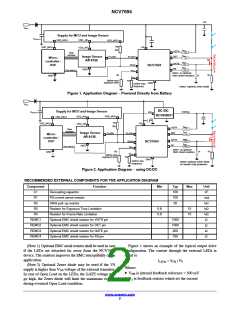
Figure 1. Application Diagram − Powered Directly from Battery
VBAT
DC /DC
Supply for MCU and Image Sensor
VString
CSUPPLY
EN
C1
NCV898031
VDD_MCU
VDD_AR
VDD_MCU
R2
VDD_MCU
VS
VDD_AR
20k
REMC1
1 kW
VSTR
Data
interface
REMC2
1 kW
Image Sensor
AR 0135
DET
FLASH
FLASH
Micro−
controller /
DSP
REMC3
200 W
GATE
FB
DIAG
RETL
NCV7694
REMC4
750 W
GND
Diag detection
Note1: 4x optional
EMC shield resistors
ZD
R3
R1
GND
RFRL
Define max
exposure time
R4
GND
Define max
frequency
Note2: Optional Zener diode
for Mosfet Gate protection
Figure 2. Application Diagram − using DC/DC
RECOMMENDED EXTERNAL COMPONENTS FOR THE APPLICATION DIAGRAM
Component
C1
Function
Min
Typ
100
100
20
Max
Unit
nF
mW
kW
kW
kW
W
Decoupling capacitor
FB current sense resistor
DIAG pull−up resistor
R1
R2
R3
Resistor for Exposure Time Limitation
Resistor for Frame Rate Limitation
0.8
0.8
15
15
R4
REMC1
REMC2
REMC3
REMC4
Optional EMC shield resistor for VSTR pin
Optional EMC shield resistor for DET pin
Optional EMC shield resistor for GATE pin
Optional EMC shield resistor for FB pin
1000
1000
200
W
W
750
W
(Note 1) Optional EMC serial resistor shall be used in case
if the LEDs are detached far away from the NCV7694
device. The resistors improves the EMC susceptibility of the
application.
Figure 1 shows an example of the typical output drive
configuration. The current through the external LEDs is
equal to
ILEDs = VFB / R1
(Note 2) Optional Zener diode may be used if the VS
Where:
supply is higher than V voltage of the external transistor.
GS
• V is internal feedback reference = 300 mV
FB
In case of Open Load on the LEDs, the GATE voltage will
go high, the Zener diode will limit the maximum voltage
during eventual Open Load condition.
• R is feedback resistor which set the current
1
www.onsemi.com
2

 ONSEMI [ ONSEMI ]