NCP698
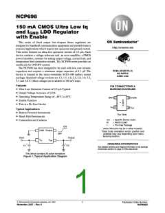
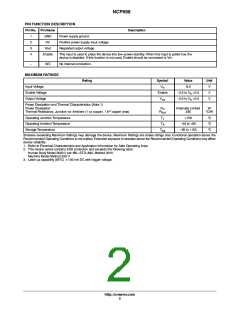
PIN FUNCTION DESCRIPTION
Pin No. Pin Name
Description
1
2
3
4
GND
Vin
Power supply ground.
Positive power supply input voltage.
Regulated output voltage.
Vout
Enable
This input is used to place the device into low-power standby. When this input is pulled low, the
device is disabled. If this function is not used, Enable should be connected to Vin.
-
N/C
No internal connection.
MAXIMUM RATINGS
Rating
Symbol
Value
Unit
V
Input Voltage
Enable Voltage
Output Voltage
V
in
6.0
Enable
-0.3 to V +0.3
in
V
V
out
-0.3 to V +0.3
in
V
Power Dissipation and Thermal Characteristics (Note 1)
Power Dissipation
Thermal Resistance, Junction-to-Ambient (1 oz copper, 1 in copper area)
P
Internally Limited
235
W
°C/W
D
2
R
ꢁ
JA
Operating Junction Temperature
T
+150
°C
°C
°C
J
Operating Ambient Temperature
T
A
-40 to +85
-55 to +150
Storage Temperature
T
stg
Stresses exceeding Maximum Ratings may damage the device. Maximum Ratings are stress ratings only. Functional operation above the
Recommended Operating Conditions is not implied. Extended exposure to stresses above the Recommended Operating Conditions may affect
device reliability.
1. Refer to Electrical Characteristics and Application Information for Safe Operating Area.
2. This device series contains ESD protection and exceeds the following tests:
Human Body Model 2000 V per MIL-STD-883, Method 3015
Machine Model Method 200 V
3. Latch up capability (85°C) "100 mA DC with trigger voltage.
http://onsemi.com
2

 ONSEMI [ ONSEMI ]