NCP1236
TYPICAL APPLICATION EXAMPLE
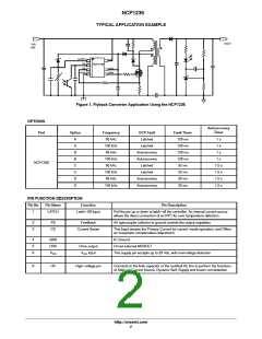
VOUT
VIN
(dc)
LATCH
HV
FB
CS
NCP1236
VCC
DRV
GND
Figure 1. Flyback Converter Application Using the NCP1236
OPTIONS
Part
Autorecovery
Timer
Option
Frequency
65 kHz
OCP Fault
Latched
Fault Timer
128 ms
128 ms
128 ms
128 ms
32 ms
A
A
B
B
C
C
D
D
1 s
1 s
100 kHz
65 kHz
Latched
Autorecovery
Autorecovery
Latched
1 s
100 kHz
65 kHz
1 s
NCP1236
1.5 s
1.5 s
1.5 s
1.5 s
100 kHz
65 kHz
Latched
32 ms
Autorecovery
Autorecovery
32 ms
100 kHz
32 ms
PIN FUNCTION DESCRIPTION
Pin No
Pin Name
Function
Pin Description
1
LATCH
Latch−Off Input
Pull the pin up or down to latch−off the controller. An internal current source
allows the direct connection of an NTC for over temperature detection
2
3
FB
CS
Feedback
An optocoupler collector to ground controls the output regulation.
Current Sense
This Input senses the Primary Current for current−mode operation, and Offers
an overpower compensation adjustment.
4
5
6
GND
DRV
IC Ground
Drive output
Drives external MOSFET
V
CC
V
CC
input
This supply pin accepts up to 28 Vdc, with overvoltage detection
8
HV
High−voltage pin
Connects to the bulk capacitor or the rectified AC line to perform the functions
of Start−up Current Source, Dynamic Self−Supply and brown−out detection
http://onsemi.com
2

 ONSEMI [ ONSEMI ]