MC10H166
LOGIC DIAGRAM
A4 9
B4 10
A3 12
B3 11
2 A ꢂ B
A2 13
B2 14
3 A ꢃ B
A1
B1
6
7
V
V
=
=
=
PIN 1
PIN 16
PIN 8
CC1
CC2
V
EE
A0
B0
5
4
ꢀE 15
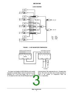
FIGURE 1 − 9−BIT MAGNITUDE COMPARATOR
A0 B0 A1 B1 A2 B2 A3 B3 A4 B4
A5 B5 A6 B6 A7 B7 A8 B8
A0
A1
A2
A3
A4
A0
A1
A2
A3
A4
B0
B1
B2
B3
B4
B0
B1
MC10H166
ꢂ B
B2
B3
B4
A
A
ꢃ
B
A ꢃ B
A
ꢂ
B
Aꢂ B
Aꢃ B
A = B
For 9−Bit Word
For longer word lengths, the MC10H166 can be serially
expanded or cascaded. Figure 1 shows two devices in a serial
expansion for a 9−bit word length. The A > B and
A < B outputs are fed to the A0 and B0 inputs respectively
of the next device. The connection for an A = B output is also
shown. The worst case delay time of serial expansion is
equal to the number of comparators times the
data−to−output delay.
http://onsemi.com
3

 ONSEMI [ ONSEMI ]