WL/WLM
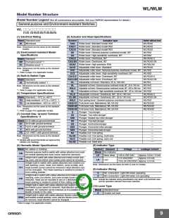
Model Number Structure
Model Number Legend (Not all combinations are possible. Ask your OMRON representative for details.)
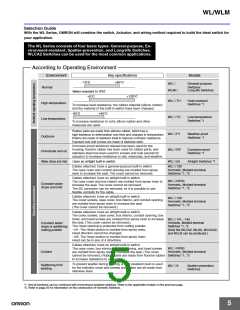
General-purpose and Environment-resistant Switches
WL @@-@@@@@@@@
(1) (2) (3) (4) (5) (6) (7) (8) (9)(10)
(1) Electrical Rating
(2) Actuator and Head Specifications
Blank Standard load
Symbol
CA2
Actuator type
Roller lever: Standard model R38
Switch without lever
WLRCA2
01
Microload
CA2-7 Roller lever: Standard model R50
CA2-8 Roller lever: Standard model R63
WLRCA2
Note: Dimensions are the same as the standard
models.
WLRCA2
(3) Environment-resistant Model
Specifications
H2
G2
Roller lever: General-purpose overtravel model, 80°
Roller lever: High-sensitivity overtravel, 80°
WLRH2
WLRG2
CA2-2 Roller lever: Overtravel, 90°
CA2-2N Roller lever: Overtravel, 90°
GCA2 Roller lever: High-precision R38
WLRCA2-2
WLRCA2-2N
WLRGCA2
WLRCA2
Blank Standard
RP Corrosion-proof *1
P1
Weather-proof *1
CA12
H12
Adjustable roller lever: Standard
Note: Dimensions are the same as the standard
models.
*1. Refer to page 4 for applicable models.
Adjustable roller lever: General-purpose overtravel model, 80° WLRH2
G12
Adjustable roller lever: High-sensitivity overtravel, 80°
WLRG2
(4) Built-in Switch Type
CA12-2 Adjustable roller lever: Overtravel, 90°
CA12-2N Adjustable roller lever: Overtravel, 90°
WLRCA2-2
WLRCA2-2N
WLRCL
Blank Standard
CL
HL
HAL4
GL
Adjustable rod lever: Standard, 25 to 140 mm
Adjustable rod lever: General-purpose overtravel model, 80
Adjustable rod lever: General-purpose overtravel model, 80
55
Hermetically sealed *1
°
°
°
, 25 to 140 mm
WLRH2
Note: Dimensions are the same as the standard
models.
*1. Refer to page 4 for applicable models.
, 350 to 380 mm WLRH2
, 25 to 140 mm WLRG2
Adjustable rod lever: High-sensitivity overtravel, 80
(5) Temperature Specifications
CL-2
Adjustable rod lever: Overtravel, 90°, 25 to 140 mm
WLRCA2-2
Blank Standard: –10°C to +80°C
TH Heat-resistant: +5°C to +120°C *1
CL-2N Adjustable rod lever: Overtravel, 90°, 25 to 140 mm
HAL5 Rod spring lever: General-purpose overtravel model, 80°
WLRCA2-2N
WLRH2
TC
Low-temperature: –40
°
C to +40
°
C *1
CA32-41 Fork lever lock: Maintained, WL-5A100
CA32-42 Fork lever lock: Maintained, WL-5A102
CA32-43 Fork lever lock: Maintained, WL-5A104
WLRCA32
WLRCA32
Note: Dimensions are the same as the standard
models.
*1. Refer to page 4 for applicable models.
WLRCA32
D
D2
Plunger: Top plunger
—
—
—
—
—
—
—
—
—
—
—
(7) Conduit Size, Ground Terminal
Specifications *2
Plunger: Top-roller plunger
Plunger: Sealed top-roller plunger
Plunger: Top-ball plunger
D28
D3
Blank G1/2 without ground terminal
G1 G1/2 with ground terminal
SD
Plunger: Horizontal plunger
Plunger: Horizontal-roller plunger
Plunger: Horizontal-ball plunger
Flexible rod: Coil spring
G
Y
Pg13.5 with ground terminal
M20 with ground terminal
SD2
SD3
NJ
TS 1/2-14NPT with ground terminal
Note: Dimensions are the same as the standard
models.
*2. Models with ground terminals are approved by
NJ-30
NJ-2
Flexible rod: Coil spring, multi-wire
Flexible rod: Coil spring, resin rod
NJ-S2 Flexible rod: Steel wire
EN/IEC (CE marking).
(6) Hermetic Model Specifications
(8) Indicator Type
Blank No cables or molding
Symbol
Element
Voltage
Leakage current
General-purpose built-in switch with cables attached and mold-
ed conduit opening and cover (cover cannot be removed). *
Blank No indicator
139
LE
LD
Neon lamp
LED
125 to 250 VAC
115 VAC/VDC
Approx. 0.6 to 1.9 mA
Approx. 0.5 mA
Airtight built-in switch with cables attached and molded conduit open-
140
ing, cover, and box interior cover screws (cover cannot be removed). *
10 to 24 VAC/VDC Approx. 0.4 mA
Airtight built-in switch with cables attached and molded con-
duit opening, cover, head, box interior, cover screws, and
141 head screws (cover cannot be removed, Head direction can-
not be changed). The Head opening is created to protect it
from cutting powder. *
Note: Dimensions are the same for both LE and LD models.
(9) Indicator Wiring
2
3
NC connection: Light-ON when operating
NO connection: Light-ON when not operating
Airtight built-in switch with cables attached and molded conduit
opening, cover, box interior, and cover screws (cover cannot be
removed, Head can be mounted in any of 4 directions). The
145
Note: Include the indicator wiring specification only when a (6) hermetic seal
and (8) operation indicator have been selected.
Head opening is created to protect it from cutting powder. *
Airtight built-in switch with cables attached and molded cover and
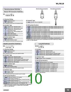
(10) Lever Type
box interior (cover cannot be removed, Head direction can be
RP40
changed). SC Connector can be removed, so it is possible to use
Blank Standard lever
flexible conduits for the cable. *
A
Double nut lever
Airtight built-in switch with cables attached, fluorine rubber used,
RP60 and molded conduit opening, cover, and box interior (cover cannot
be removed, Head direction cannot be changed). *
* Refer to page 4 for applicable models.
9

 OMRON [ OMRON ELECTRONICS LLC ]