WL/WLM
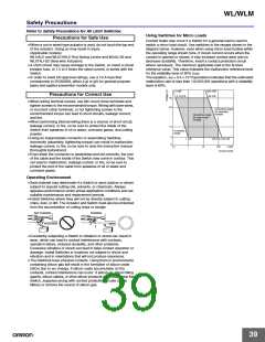
Built-in Switch
Connectors
Do not remove or replace the built-in switch. If the position of the built-
in switch moves, it can cause reduced performance, and if the
insulation sheet moves (separator), the insulation may become
ineffective.
Either the easy-to-use Allen-head nut or the SC Connector can be
used as connectors. To ensure high-sealing properties, use the SC
Connector. Refer to Limit Switch Connectors for details on SC
Connectors.
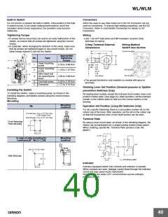
Tightening Torque
Wiring
• If screws are too loose they can lead to an early malfunction of the
Switch, so ensure that all screws are tightened using the correct
torque.
• In particular, when changing the direction of the Head, make sure
that all screws are tightened again to the correct torque. Do not
allow foreign objects to fall into the Switch.
• Use 1.25-mm2 lead wires and M4-insulation covered crimp
terminals for wiring.
Crimp Terminal External
Dimensions
Wiring Method
Switch Box Section
L
Ground terminal
F
l
Appropriate
tightening
torque
No.
Type
D dia.
B
1.
6.
Head mounting
screw
3.
1.
2.
0.78 to 0.88 N·m
1.18 to 1.37 N·m
dz dia.: 4.3
D dia. : 4.5
B
L
F
l
dz dia.
Cover mounting
screw
: 8.5
: 21.0
: 7.8
NO terminal
NC terminal
Allen-head bolt
3. (for securing the
lever)
4.
2.
: 9.0 (mm)
4.90 to 5.88 N·m
• The ground terminal is only installed on models with ground
terminals.
4. Terminal screw
5. Connector
0.59 to 0.78 N·m
1.77 to 2.16 N·m
5.
Rotating Lever Set Position (General-purpose or Spatter-
prevention Switches Only)
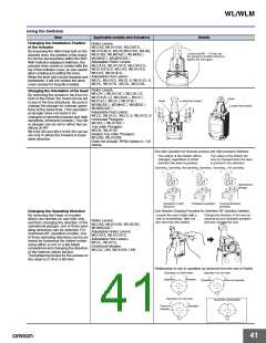
Installing the Switch
To install the Switch, make a mounting panel, as shown in the
following diagram, and tighten screws using the correct torque.
Mounting
Mounting
All rotating lever models, except the fork lever lock models, have a set
position marker plate. (See page 23.) After operation, set the indicator
needle on the marker plate so that is in the convex section of the
bearing.
Mounting
locations
WL
Operation Set Position (Long-life Switches Only)
For all Long-life Switching, there is a set position marker slit on the
rubber cap of the head. After operation, set the slit on the rubber cap
so that the fluorescent color on the shaft section can be seen.
Front Mountig :Four, 5.2+0.2
dia. holes
0
or M5 tapped holes
Rear Mountig : Four, 6.2+0.2
dia. holes
0
Terminal Plate
Front Mountig/
By using a short circuit plate, as shown in the following diagram, the
Switch can be fabricated into a single-polarity double-break switch.
When ordering, specify WL Terminal Plate (product code: WL-
9662F).
Rear Mountig
58.7 0.15
30.2 0.15
9
2.5+0.2
7.1
0
In case of side mounting for
overtravel,90° WL@-@@2N
Mounting
locations
3R
COM
9
0.2
23 0.4
16 0.15
Two, 5.2 +0.2 dia. holes
0
7
2R
Side Mountig
3.5
2.1R
64 0.15
4.2+0.1
t = 0.6 Brass plate
0
Indicator
Indicator-equipped switch has contacts and indicator in parallel.
When contacts are open, leakage current flows through the indicator
circuit and may cause load's malfunction.
23 0.15
Please check the load's OFF current before use the indicator-
equipped switch.
40

 OMRON [ OMRON ELECTRONICS LLC ]