WL/WLM
Safety Precautions
Refer to Safety Precautions for All Limit Switches.
Using Switches for Micro Loads
Precautions for Safe Use
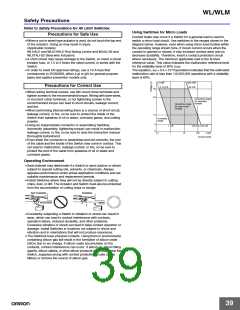
Contact faults may occur if a Switch for a general-load is used to
switch a micro load circuit. Use switches in the ranges shown in the
diagram below. However, even when using micro load models within
the operating range shown here, if inrush current occurs when the
contact is opened or closed, it may increase contact wear and so
decrease durability. Therefore, insert a contact protection circuit
where necessary. The minimum applicable load is the N-level
reference value. This value indicates the malfunction reference level
for the reliability level of 60% (λ60).
• When a rod or wired-type actuator is used, do not touch the top end
of the actuator. Doing so may result in injury.
(Applicable models)
WLHAL5 and WL01HAL5 Rod Spring Levers and WLNJ-S2 and
WL01NJ-S2 Steel-wire Actuators.
• A short-circuit may cause damage to the Switch, so insert a circuit
breaker fuse, of 1.5 to 2 times the rated current, in series with the
Switch.
• In order to meet EN approval ratings, use a 10-A fuse that
corresponds to IEC60269, either a gI or gG for general-purpose
types and spatter-prevention models only.
The equation, λ60 = 0.5 × 10⁻⁶/operations indicates that the estimated
malfunction rate is less than 1/2,000,000 operations with a reliability
level of 60%.
5 mW
800 mW
26 mA
Precautions for Correct Use
0.16 mA
30
24
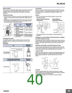
• When wiring terminal screws, use M4 round crimp terminals and
tighten screws to the recommended torque. Wiring with bare wires,
or incorrect crimp terminals, or not tightening screws to the
recommended torque can lead to short-circuits, leakage current,
and fire.
Operating range
for standard
models
Operating range
for micro-load
models
• When performing internal wiring there is a chance of short-circuit,
leakage current, or fire, so be sure to protect the inside of the
Switch from splashes of oil or water, corrosive gases, and cutting
powder.
• Using an inappropriate connector or assembling Switches
incorrectly (assembly, tightening torque) can result in malfunction,
leakage current, or fire, so be sure to read the instruction manual
thoroughly beforehand.
12
Unusable
range
5
0
1 mA
1
100 mA 160 mA
0.1
10
100
1,000
Current (mA)
• Even when the connector is assembled and set correctly, the end
of the cable and the inside of the Switch may come in contact. This
can lead to malfunction, leakage current, or fire, so be sure to
protect the end of the cable from splashes of oil or water and
corrosive gases.
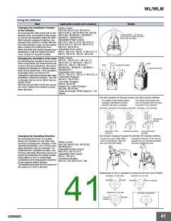
Operating Environment
• Seal material may deteriorate if a Switch is used outdoor or where
subject to special cutting oils, solvents, or chemicals. Always
appraise performance under actual application conditions and set
suitable maintenance and replacement periods.
• Install Switches where they will not be directly subject to cutting
chips, dust, or dirt. The Actuator and Switch must also be protected
from the accumulation of cutting chips or sludge.
Not Suitable
Suitable
• Constantly subjecting a Switch to vibration or shock can result in
wear, which can lead to contact interference with contacts,
operation failure, reduced durability, and other problems.
Excessive vibration or shock can lead to false contact operation or
damage. Install Switches in locations not subject to shock and
vibration and in orientations that will not produce resonance.
• The Switches have physical contacts. Using them in environments
containing silicon gas will result in the formation of silicon oxide
(SiO2) due to arc energy. If silicon oxide accumulates on the
contacts, contact interference can occur. If silicon oil, silicon filling
agents, silicon cables, or other silicon products are present near the
Switch, suppress arcing with contact protective circuits (surge
killers) or remove the source of silicon gas.
39

 OMRON [ OMRON ELECTRONICS LLC ]