Connections (Common)
I Input Connections
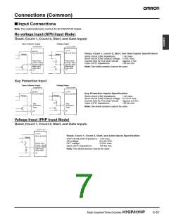
Note: The undermentioned is common for all H7GP/H7HP models.
No-voltage Input (NPN Input Mode)
Reset, Count 1, Count 2, Start, and Gate Inputs
Open Collector Output
Voltage Output
H7GP/H7HP
12 VDC
(12 to 24 VDC)
(12 to 24 VDC)
Reset, Count 1, Count 2, Start, and Gate Inputs Specification
Short-circuit (ON) impedance: 1 kΩ max.
Sensor
Sensor
Short-circuit (ON) residual voltage: 2 VDC max.
Reset input
Count 1 input
Count 2 input
Start input
Gate input
0 V
Reset input
Count 1 input
Count 2 input
Start input
Current flow for 0-Ω short-circuit:
Open (OFF) impedance:
Approx. 2 mA
100 kΩ min.
Note: Two-wired sensors cannot be used.
Gate input
Key Protection Input
Open Collector Output
Voltage Output
H7GP/H7HP
12 VDC
(12 to 24 VDC)
Sensor
Key Protection Inputs Specification
(12 to 24 VDC)
Sensor
Short-circuit (ON) impedance:
1 kΩ max.
Short-circuit (ON) residual voltage: 0.5 VDC max.
Current flow for 0-Ω short-circuit:
Open (OFF) impedance:
Approx. 0.5 mA
100 kΩ min.
Key
protection
input
Key
protection
input
Note: Two-wired sensors cannot be used.
0 V
Voltage Input (PNP Input Mode)
Reset, Count 1, Count 2, Start, and Gate Inputs
Reset, Count 1, Count 2, Start, and Gate Inputs Specification
(12 to 24 VDC)
Sensor
Short-circuit (ON) impedance: 1 kΩ max.
ON voltage:
9 to 24 VDC
5 VDC max.
100 kΩ min.
Reset input
Count 1 input
Count 2 input
Start input
OFF voltage:
Open (OFF) impedance:
Note: Two-wired sensors cannot be used.
Gate input
Total Counter/Time Counter H7GP/H7HP
C-57

 OMRON [ OMRON ELECTRONICS LLC ]