H7E@-N@P
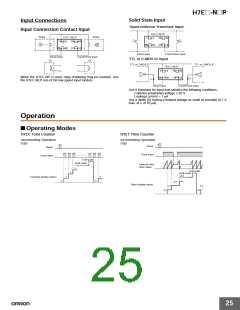
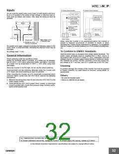
Inputs
PC Board (Bad Example)
PC Board (Good Example)
Do not route the wiring of the count, timer, or reset inputs in the vicin-
ity of, or in parallel to the wiring of high-voltage or inductive load cir-
cuits (such as motors and relays). Also, keep the wiring as short as
possible.
H7E@-N@P
Large-current-
consuming
components
Placed far away from
the power supply.
Large-current-
consuming
components
Wired in parallel
with large-
current-carrying
components.
H7E@-N@P
Bypass
Bypass
capacitor
capacitor
H7E@-N@P
Power supply
Power supply
When using the Counter in an environment where the Counter is
subject to frequent occurrences of vibration or shock, or when
mounting the Counter facing downwards or sideways, it is suggested
that the Counter be directly soldered to a PCB instead of using sock-
ets.
Be careful not to apply voltages exceeding the following values to the
count, timer, or reset terminals, otherwise the internal circuit may be
damaged.
To Conform to EN/IEC Standards
No-voltage input: 3 VDC
Input terminals have no insulation from power supply terminals. The
power supply terminals must be supplied from a SELV source in
accordance with IEC61010-1 Annex H. SELV (separated extra-low
voltage) source is a power supply having double or reinforced insula-
tion between the primary and the secondary circuit and having out-
put voltage of 30 V rms max. and 42.4 V peak max. or 60 VDC max.
General Information
Finish soldering under the conditions below.
Solder the terminals within 5 seconds, at a solder iron tip tempera-
ture of 250°C 10°C when using lead solder, and within 3 seconds,
at a solder iron tip temperature of 350°C 10°C when using lead-
free solder.
Cleaning
Since the Counter is not flux-tight, do not use flux when soldering.
To prevent damage, the exterior of the Counter must not be exposed
to organic solvents (3.g. paint thinner or benzine), strong alkalis, or
strong acids.
Avoid automatic and dip soldering. Manually solder the Counter onto
a PC board, and avoid cleaning as much as possible.
When mounting the Counter on a PC board with components which
consume higher current than the H7E@-N@P, observe the following
precautions.
Others
• No user-serviceable parts.
1. Minimize the wiring (less than 50 mm) from the H7E@-N@P to the
• Return to OMRON for all repairs.
power supply section.
2. Avoid placing the H7E@-N@P power, timer, counter, or reset input
circuit in parallel with circuits that consume large currents, partic-
ularly on the positive side.
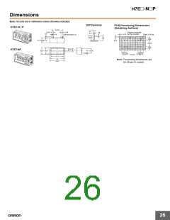
ALL DIMENSIONS SHOWN ARE IN MILLIMETERS.
To convert millimeters into inches, multiply by 0.03937. To convert grams into ounces, multiply by 0.03527.
In the interest of product improvement, specifications are subject to change without notice.
32

 OMRON [ OMRON ELECTRONICS LLC ]