H7E@-N@P
AC/DC Multi-voltage Input Models
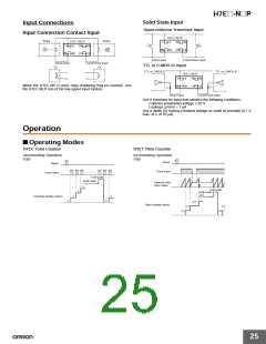
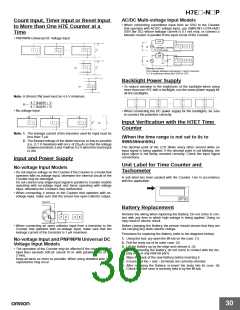
Count Input, Timer Input or Reset Input
to More than One H7E Counter at a
Time
• When connecting count/timer input from an SSR to the Counter
that operates with AC/DC voltage input, use OMRON’s G3TA-IA/ID
SSR (for DC) whose leakage current is 0.1 mA max. or connect a
bleeder resistor in parallel to the input circuit of the Counter.
• PNP/NPN Universal DC Voltage Input
or
Leakage current:
0.1 mA max.
or
or
or
*Bleeder resistor
The voltage between terminals 1 and 2 must be
1.5 V maximum when the SSR is OFF.
Backlight Power Supply
• To reduce variation in the brightness of the backlight when using
more than one H7E with a backlight, use the same power supply for
all the backlights.
or
Note: H (Reset ON) level must be 4.5 V minimum.
4.7 (kΩ)/N + V
H =
4.7 (kΩ)/N + R
• No-voltage Input
• When connecting the DC power supply for the backlights, be sure
to connect the polarities correctly.
or
Input Verification with the H7ET Time
Counter
Note: 1. The leakage current of the transistor used for input must be
less than 1 µA.
(When the time range is not set to 0s to
999h59min59s)
The decimal point of the LCD blinks every other second while an
input signal is being applied. If the decimal point is not blinking, the
input signal is not being received correctly. Check the input signal
connections.
2. The forward voltage of the diode must be as low as possible
(i.e., 0.1 V maximum with an IF of 20 µA) so that the voltage
between terminals 3 and 4 will be 0.5 V when the reset input
is ON.
Input and Power Supply
Unit Label for Time Counter and
Tachometer
A unit label has been packed with the Counter. Use in accordance
with the application.
No-voltage Input Models
• Do not impose voltage on the Counter if the Counter is a model that
operates with no-voltage input, otherwise the internal circuit of the
Counter may be damaged.
Do not connect any single input signal in parallel to Counter models
operating with no-voltage input and those operating with voltage
input, otherwise the Counters may malfunction.
• When connecting a sensor to the Counter that operates with no-
voltage input, make sure that the sensor has open collector output.
Sensor
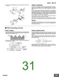
Battery Replacement
Remove the wiring when replacing the Battery. Do not come in con-
tact with any item to which high voltage is being applied. Doing so
may result in electric shock.
1
2
3
4
• When connecting an open collector input from a transistor to the
Counter that operates with no-voltage input, make sure that the
leakage current of the transistor is 1 µA maximum.
Before changing the Battery, the person should ensure that they are
not carrying any static electric charge.
Procedure for replacing the Battery (refer to the diagrams below):
1. Using the tool, pry open the lift-tab on the case. (1)
2. Pull the body out of its outer case. (2)
No-voltage Input and PNP/NPN Universal DC
Voltage Input Models
• The operation of the Counter may be affected if the capacitance of
input lines exceeds 500 pF (about 10 m, with parallel wires of 2 x
2 mm).
3. Lift the Battery up by the edge and remove it. (3)
When removing the Battery, do not come in contact with the dis-
play area or any internal parts.
4. Wipe the back of the new Battery before inserting it.
5. Ensure that the + and – terminals are correctly oriented.
Keep all wires as short as possible. When using shielded wire, line
capacitance may occur.
6. After replacing the Battery, re-insert the body into its case. (4)
Check that the case is securely held in by the lift-tab.
30

 OMRON [ OMRON ELECTRONICS LLC ]