H7E@-N@P
7. Press the Reset Key before use (not necessary for H7ER-N,-NV,-
EN/IEC Standards
NV1). (5)
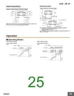
The count or timer input, reset input, and backlight power supply ter-
minals of the no-voltage input or PNP/NPN universal DC voltage
input models (H7E@-N,-N1, H7E@-NV(-H),-NV1(-H)) are not iso-
lated.
Tool
(2)
(1)
A SELV power supply conforming to Appendix H of IEC61010-1
should be used for the count or timer input, reset input and backlight
power supply terminals. A SELV power supply is a power supply for
which the input and output have double or reinforced insulation, and
for which the output voltage is 30 Vrms with 42.4 V peak or 60 VDC
max. (Only the H7E@-NV@-H has a backlight.)
(1)
Battery
(3)
The terminals for count or timer input and reset input for AC/DC
multi-voltage input models have basic insulation.
Connect the reset input terminals to a device that does not have
exposed current-carrying parts and has basic insulation for 240 VAC.
(4)
Others
If the indicator keeps flickering or is OFF, the internal battery may be
close to the end of its service life. In such a case, it is suggested that
the battery be replaced.
(5)
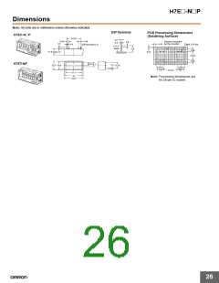
■ PCB-mounting Counter
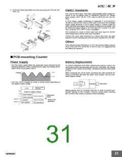
Power Supply
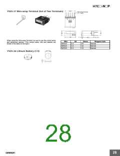
Battery Replacement
• Use the power supply within the applicable range indicated by the
following waveform, while considering the ripple and voltage fluctu-
ations of the circuit power source.
To prevent unwanted reset when replacing the battery, connect the
new battery before disconnecting the old one. Otherwise, the voltage
supplied to the counter circuit drops, causing the present count value
to reset.
3.6 V
Voltage
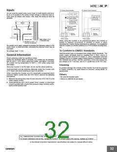
When designing the circuit board, providing two extra terminals for
battery connection will make the switch must simpler. See the sche-
matic diagram below:
2.6 V
• The H7E@-N@P changes its mode as shown below depending on
the applied supply voltage.
H7E@-N@P
Internal circuit
operation
LCD
Wiring polarity must be carefully observed, in order to prevent per-
manent damage to the Counters. Exercise caution when inserting
the Counter in the socket, to prevent reversed polarity.
(V)
3.6
3
Beyond supply voltage
Looks darker
Applicable
range
Normal operation
Looks normal
Flashes
Approx. 2.6
Normal operation
Battery life
guideline
Approx. 2.2
0
No display
No operation
31

 OMRON [ OMRON ELECTRONICS LLC ]