E2E
43
38
12
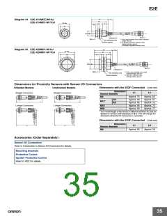
Diagram 34 E2E-X14MD@-M1GJ
E2E-X14MD1-M1TGJ
29 dia.
24
4
10
10
14.8 dia.
*1
M12 × 1
Indicators*2
M18 × 1
*1. 6-dia. vinyl-insulated round cable, Standard
length: 300 mm
Two clamping nuts
Toothed washer
*2. D1 Models: Operation indicator (red),
Setting indicator (green)
D2 Models: Operation indicator (red)
Diagram 36 E2E-X20MD1-M1GJ
E2E-X20MD1-M1TGJ
48
43
12
42 dia.
36
13
5
10
26.8 dia.
*1
M12 × 1
Indicators*2
M30 × 1.5
*1. 6-dia. vinyl-insulated round cable,
Two clamping nuts
Toothed washer
Standard length: 300 mm
*2. Operation indicator (red),
Setting indicator (green)
Dimensions for Proximity Sensors with Sensor I/O Connectors
Dimensions with the XS2F Connected (Unit:mm)
Shielded Models
Unshielded Models
Dimension
Sensor diameter
L1
L2
Straight Connectors
Straight Connectors
M8
Approx. 75
Approx. 80
Approx. 85
Approx. 85
Approx. 90
Approx. 62
Approx. 67
Approx. 72
Approx. 72
Approx. 77
DC
M12*
AC
L1
L1
L-shape Connectors
L-shape Connectors
M18
M30
* The overall length of the Sensor is different between AC and DC
Models for Sensors with diameters of M12. This will change the
dimension when the I/O Connector is connected.
Dimensions with the XS3F Connected (Unit:mm)
Dimension
Sensor diameter
L2
L2
L1
L2
M8
Approx. 65
Approx. 54
Accessories (Order Separately)
Sensor I/O Connectors
Refer to Introduction to Sensor I/O Connectors for details.
Mounting Brackets
Protective Covers
Sputter Protective Covers
Refer to Y92@ for details.
35

 OMRON [ OMRON ELECTRONICS LLC ]