E2E
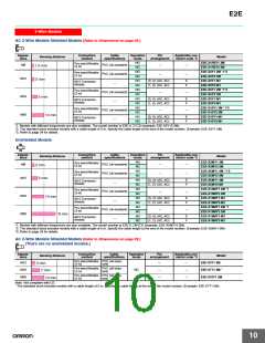
E2E-X@Y@ AC 2-Wire Models
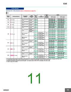
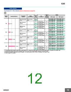
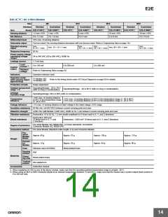
Size
M8
M12
M18
M30
Shielded
Shielded
Unshielded
Shielded
Unshielded
Shielded
Unshielded
Shielded
Unshielded
Item
Model E2E-X1R5Y@
E2E-X2MY@
2 mm 10%
0 to 1.6 mm
E2E-X2Y@
E2E-X5MY@
5 mm 10%
0 to 4 mm
E2E-X5Y@
E2E-X10MY@ E2E-X10Y@
10 mm 10%
E2E-X18MY@
18 mm 10%
0 to 14 mm
Sensing distance
Set distance
1.5 mm 10%
0 to 1.2 mm
0 to 8 mm
Differential travel
Detectable object
10% max. of sensing distance
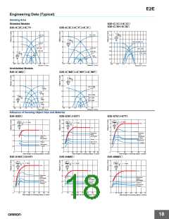
Ferrous metal (The sensing distance decreases with non-ferrous metal. Refer to Engineering Data on page 19.)
Standard sensing
object
Iron,
8 × 8 × 1 mm
Iron,
Iron,
Iron,
54 × 54 × 1 mm
Iron, 12 × 12 × 1 mm
Iron, 30 × 30 × 1 mm
15 × 15 × 1 mm 18 × 18 × 1 mm
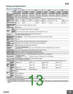
Response frequency
25 Hz
Power supply voltage
(operating voltage
range)*1
24 to 240 VAC (20 to 264 VAC), 50/60 Hz
1.7 mA max.
Leakage current
Load
5 to 100 mA
5 to 200 mA
5 to 300 mA
current *2
Control
output
Residual
voltage
Refer to Engineering Data on page 20.
Operation indicator (red)
Y1 Models: NO
Indicators
Operation mode
(with sensing object
approaching)
Refer to the timing charts under I/O Circuit Diagrams on page 23 for details.
Y2 Models: NC
Protection circuits
Surge suppressor
Ambient temperature Operating/Storage: −25 to 70°C
Operating/Storage: −40 to 85°C (with no icing or condensation)
range *1*2
(with no icing or condensation)
Ambient
Operating/storage: 35% to 95% (with no condensation)
10% max. of sensing distance
humidity range
Temperature
influence
15% max. of sensing distance at 23°C in the temperature range of −40 to 85°C,
at 23°C in the temperature range
10% max. of sensing distance at 23°C in the temperature range of −25 to 70°C
of −25 to 70°C
Voltage influence
1% max. of sensing distance at rated voltage in the rated voltage 15% range
Insulation resistance 50 MΩ min. (at 500 VDC) between current-carrying parts and case
Dielectric strength
Vibration resistance
4,000 VAC (M8 Models: 2,000 VAC), 50/60 Hz for 1 min between current-carrying parts and case
Destruction: 10 to 55 Hz, 1.5-mm double amplitude for 2 hours each in X, Y, and Z directions
Destruction: 500 m/s2
Shock resistance
10 times each in X, Y, and
Z directions
Destruction: 1,000 m/s2 10 times each in X, Y, and Z directions
Pre-wired Models: IEC 60529 IP67, in-house standards: oil-resistant
Connector Models: IEC 60529 IP67
Degree of protection
Connection method
Pre-wired Models (Standard cable length: 2 m) and Connector Models
Pre-
wired
Models
Approx. 60 g
Approx. 15 g
Approx. 70 g
Approx. 130 g
Approx. 40 g
Approx. 175 g
Approx. 90 g
Model
Weight
Connec-
tor
Models
Approx. 25 g
Case
Stainless steel (SUS303)
PBT
Nickel-plated brass
Sensing
surface
Materials
Clamp-
ing nuts
Nickel-plated brass
Toothed
washer
Zinc-plated iron
Accessories
Instruction manual
*1. When supplying 24 VAC to any of the above models, make sure that the operating ambient temperature range is at least −25°C.
*2. When using an M18 or M30 Connector Model at an ambient temperature between 70 and 85°C, make sure that the Sensor has a control output (load current) of
5 to 200 mA max.
14

 OMRON [ OMRON ELECTRONICS LLC ]