E2E
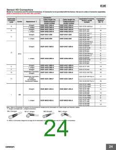
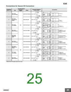
Connections for Sensor I/O Connectors
Proximity Sensor
Connection
diagram No.
Sensor I/O Connector
Connections
Operation
mode
model number
Type
Model
1: Straight
2: L-shape
E2E
XS2F
1
2
3
4
1
2
3
4
DC 2-wire
Brown (+)
1
2
3
4
5
6
7
8
9
E2E-X@D1-M1G(J) XS2F-D42@-@A0-A
(IEC pin wiring)
D: 2-m cable
G: 5-m cable
Blue (−)
1: Straight
2: L-shape
E2E
XS2F
DC 2-wire
(previous pin
wiring)
1
2
3
4
1
2
3
4
E2E-X@D1-M1
XS2F-D42@-@D0
Blue (−)
Brown (+)
D: 2-m cable
G: 5-m cable
1: Straight
2: L-shape
E2E
XS2F
1
2
3
4
1
2
3
4
DC 2-wire
(no polarity)
NO
E2E-X@D1-M1J-T
E2E-X@D1-M3G
E2E-X@D1S-M1
XS2F-D42@-@D0
Blue (+) (−)
Brown (−) (+)
D: 2-m cable
G: 5-m cable
1: Straight
2: L-shape
E2E
XS3F
*
1
1
2
3
4
Brown (+)
DC 2-wire
(M8 connector)
XS3F-M42@-40@-A
2
3
4
White (not connected)
Blue (not connected)
Black (−)
2: 2-m cable
5: 5-m cable
1: Straight
2: L-shape
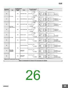
E2E
XS2F
*
DC 2-wire
(diagnostic
type)
1
2
3
4
1
2
3
4
Brown (not connected)
White (diagnostic output) (+)
Blue (0 V)
XS2F-D42@-@80-A
Black (control output) (+)
D: 2-m cable
G: 5-m cable
1: Straight
2: L-shape
E2E
E2E
E2E
E2E
XS2F
*
*
1
2
3
4
1
2
3
4
Brown (+)
DC 2-wire
(IEC pin wiring)
E2E-X@D2-M1G(J) XS2F-D42@-@80-A
White (−)
Blue (not connected)
Black (not connected)
D: 2-m cable
G: 5-m cable
1: Straight
2: L-shape
XS2F
DC 2-wire
(previous pin
wiring)
1
2
3
4
1
2
3
4
Brown (not connected)
White (+)
Blue (−)
Black (not connected)
E2E-X@D2-M1
XS2F-D42@-@80-A
D: 2-m cable
G: 5-m cable
NC
1: Straight
2: L-shape
XS2F
*
1
1
2
3
4
Brown (+)(−)
White (−)(+)
Blue (not connected)
Black (not connected)
DC 2-wire
(no polarity)
E2E-X@D2-M1J-T
E2E-X@D2-M3G
XS2F-D42@-@80-A
2
3
4
D: 2-m cable
G: 5-m cable
1: Straight
2: L-shape
XS3F
*
1
1
2
3
4
Brown (+)
White (−)
Blue (not connected)
Black (not connected)
DC 2-wire
(M8 connector)
2
3
4
XS3F-M42@-40@-A
2: 2-m cable
5: 5-m cable
* Different from Proximity Sensor wire colors.
25

 OMRON [ OMRON ELECTRONICS LLC ]