E2E
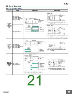
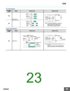
AC 2-Wire Models
Operation
Model
Timing Chart
Output circuit
mode
Present
Not present
ON
Sensing
object
Brown 3 (or 1)
Load
Operation
NO
OFF
indicator (red)
Proximity
Sensor
main
Operate
Control output
Reset
circuit
E2E-X@Y@
E2E-X@Y@-M1
Blue 4 (or 2)
Present
Not present
ON
Sensing
object
Operation
Note: For Connector Models, the connection
between pins 3 and 4 uses an NO
contact, and the connection between
pins 1 and 2 uses an NC contact.
NC
indicator (red)
OFF
Operate
Reset
Control
output
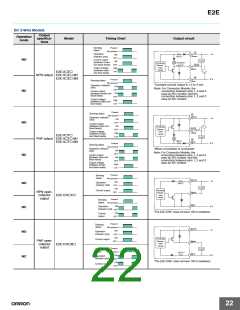
AC/DC 2-Wire Models
Operation
Model
Timing Chart
Output circuit
mode
Unstable
sensing
area
Brown
Load
Set position
Non-sensing
area
Stable sensing area
Proximity Sensor
Proximity
Sensor
main
Power
supply
Sensing
object
24 to 240 VDC
48 to 240 VAC
circuit
100 80
0
(%)
NO
E2E-X@T1
Blue
Rated
sensing
distance
ON
Setting indicator
(green)
OFF
ON
Note: The load can be connected to either the +V or
0 V side.
Operation
indicator (red)
OFF
ON
There is no need to be concerned about the
polarity (brown/blue) of the Proximity Sensor.
Control output
OFF
23

 OMRON [ OMRON ELECTRONICS LLC ]