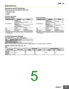
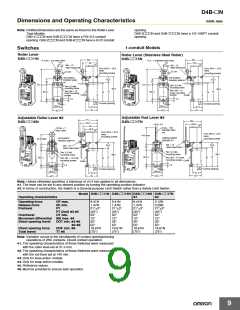
D4B-@N
Dimensions and Operating Characteristics
(Unit: mm)
Note: Omitted dimensions are the same as those for the Roller Lever
Type Models
opening.
D4B-3@@@N and D4B-7@@@N have a 1/2-14NPT conduit
opening.
D4B-1@@@N and D4B-5@@@N have a PG13.5 conduit
opening. D4B-2@@@N and D4B-6@@@N have a G1/2 conduit
1-conduit Models
Switches
Roller Lever
D4B-@@11N
Roller Lever (Stainless Steel Roller)
D4B-@@15N
62
1
62
1
17.5 dia. × 6.6 resin roller
17.5 × 7 stainless steel roller
56
56
16
16
M5 × 12
Allen-head bolt
M5 × 12
Allen-head bolt
28.3
28.3
Four, M3.5 × 19.5
head
mounting screws
Four, M3.5 × 19.5
head
mounting screws
31.5R
31.5R
Set position
indicator plate
*1
Set position
indicator plate *1
22.5
22.5
23
23
11.5
11.5
131.3 1.2
131.3 1.2
Two, 5.3 dia.
mounting holes
Two, 5.3-dia.
mounting holes
99.5
99.5
Two, M4 × 12
60 0.2
Two, M4 × 12
cover mounting
screws
77
74
77
74
60 0.2
8
cover mounting
Cover
screws
Cover
7.3
7.3
8
5.3
15
31.5
43
5.3
15
Conduit opening
Conduit opening
30 0.2
30 0.2
31.5
43
40+1
40+1
0
0
Adjustable Rod Lever *2
Adjustable Roller Lever *2
D4B-@@16N
71
64.4
53
46.8
1
66
1
D4B-@@17N
5.4
56.8
28.3
16
3 dia. × 160
stainless steel
rod
19 dia. × 7
resin roller
16
28.3
Four, M3.5 × 24.5
head
mounting screws
Four, M3.5 × 24.5
head
mounting screws
145 max.
Setting position
indicator *1
Set position
indicator plate *1
25 to 89R
23
1
2
3
M5 × 12
Allen-head bolts
22.5
22.5
M5 × 16
Allen-head bolts
23
Two, 5.3-dia.
mounting holes
Two, 5.3-dia.
99.5
99.5
mounting holes
60 0.2
77
74
77
74
60 0.2
8
Two, M4 × 12 cover
Two, M4 × 12 cover
mounting screws
mounting screws
Cover
Cover
7.3
7.3
8
5.3
15
31.5
43
5.3
15
Conduit opening
Conduit opening
30 0.2
30 0.2
31.5
43
40+1
40+1
0
0
Note: Unless otherwise specified, a tolerance of 0.4 mm applies to all dimensions.
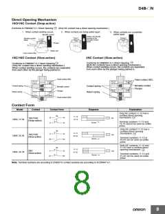
*1. The lever can be set to any desired position by turning the operating position indicator.
*2. In terms of construction, the Switch is a General-purpose Limit Switch rather than a Safety Limit Switch.
Model D4B-@@11N D4B-@@15N D4B-@@16N D4B-@@17N
Operating characteristics
*1
*2
Operating force
Release force
Pretravel
OF max.
RF min.
PT
PT (2nd) *3 *5
OT min.
9.41N
1.47N
21° 3°
(45°)
50°
12°
35°
55°
19.61N
(75°)
9.41N
1.47N
21° 3°
(45°)
50°
12°
35°
55°
19.61N
(75°)
9.41N
1.47N
21° 3°
(45°)
50°
12°
35°
55°
19.61N
(75°)
2.12N
0.29N
21° 3°
(45°)
50°
12°
35°
55°
19.61N
(75°)
Overtravel
Movement differential MD max. *4
Direct opening travel
DOT min. *3 *6
*4 *6
DOF min. *6
TT *5
Direct opening force
Total travel
Note: Variation occurs in the simultaneity of contact opening/closing
operations of 2NC contacts. Check contact operation.
*1. The operating characteristics of these Switches were measured
with the roller level set at 31.5 mm.
*2. The operating characteristics of these Switches were measured
with the rod level set at 140 mm.
*3. Only for slow-action models.
*4. Only for snap-action models.
*5. Reference values.
*6. Must be provided to ensure safe operation.
9

 OMRON [ OMRON ELECTRONICS LLC ]