CP1E-E@@D@-@ CP1E-N@@D@-@/NA20D@-@
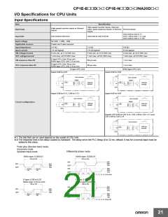
Output Specifications
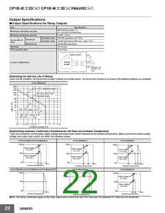
●Output Specifications for Relay Outputs
Item
Specification
250 VAC/2 A (cosφ = 1)
Maximum switching capacity
Minimum switching capacity
2 A, 24 VDC (4 A/common)
5 VDC, 10 mA
Resistive load 200,000 operations (24 VDC)
Inductive load 70,000 operations (250 VAC, cosφ = 0.4)
20,000,000 operations
Electrical
Service life of
relay
Mechanical
ON delay
15 ms max.
OFF response time
15 ms max.
Output indicator
OUT
Internal
circuits
Circuit configuration
OUT
COM
250 VAC, 2A,
24 VDC, 2 A
max.
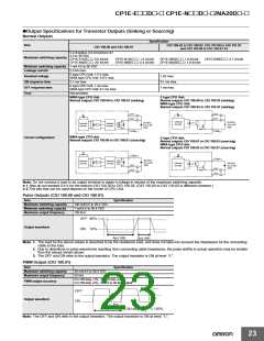
Estimating the Service Life of Relays
Under normal conditions, the service life of output contacts is as shown above. The service life of relays is as shown in the following diagram as a guideline
CP1E-@@DR-@
1000
700
500
125-VAC resistive load
300
30-VDC/250-VAC
200
resistive load
100
70
50
30
20
125 VAC cosφ= 0.4
10
7
5
250 VAC cosφ= 0.4/
30 VDC, τ = 7ms
3
2
1
0.1
0.2 0.3 0.5 0.7
1
2
3
5
7 10
Contact current (A)
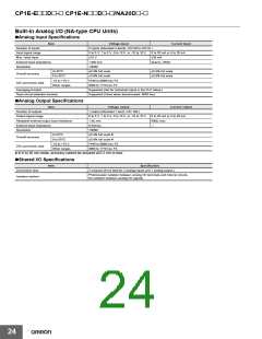
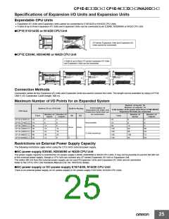
Relationship between Continuous Simultaneous ON Rate and Ambient Temperature
There are restrictions on the power supply voltage and output load current imposed by the ambient temperature. Make sure that the power supply
voltage and output load current are within the following ranges.
CP1E-N14DR-D/CP1E-N20DR-D
CP1E-N30DR-D
CP1E-N40DR-D
100
%
100%
100%
50%
Power voltage
21.6 VDC
Power voltage
21.6 VDC
Power voltage
21.6 VDC
50%
50%
0%
Power voltage
20.4 VDC
Power voltage
20.4 VDC
Power voltage
20.4 VDC
0%
0%
40 45
55˚C
35
45
55˚C
30
45 50 55˚C
Ambient temperature
Ambient temperature
Ambient temperature
CP1E-@14DR-A/CP1E-@20DR-A/CP1E-N20DT@-@
CP1E-NA20DR-A
CP1E-N60DR-D
100%
100%
80%
100%
50%
Power voltage
21.6 VDC
50%
Power voltage
20.4 VDC
0%
0%
0%
50 55˚C
Ambient temperature
40 45
Ambient temperature
55˚C
5055°C
Ambient temperature
Note: The above restrictions apply to the relay output load current from the CPU Unit even if Expansion I/O Units are not connected.
22

 OMRON [ OMRON ELECTRONICS LLC ]