CP1E-E@@D@-@ CP1E-N@@D@-@/NA20D@-@
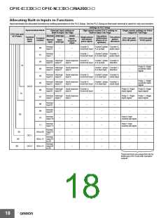
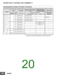
Allocating Built-in Output Terminals to Functions
Output terminals are allocated functions by setting parameters in the PLC Setup. Set the PLC Setup so that each terminal is used for only one function.
Setting in PLC Setup
When a pulse output instruction
(SPED, ACC, PLS2, or ORG) is
executed
Output terminal
block
Other than those
shown right
When the PWM
instruction is executed
Origin search setting on
Pulse Output 0/1 Tab Page
CPU Unit with
I/O points
Variable duty ratio
pulse output
Fixed duty ratio pulse output
Terminal
block label number
Terminal
Normal output
Pulse + direction
Use
PWM output
00
01
02
Normal output 0
Normal output 1
Normal output 2
Normal output 3
Normal output 4
Normal output 5
Normal output 6
Normal output 7
Pulse output 0 (pulse)
--
--
Pulse output 1 (pulse)
--
--
--
PWM output 0
10
Pulse output 0 (direction)
--
--
--
--
--
--
--
--
--
03
Pulse output 1 (direction)
CIO 100
04
Pulse 0: Error counter reset
output
--
--
--
--
--
--
--
14
Pulse 1: Error counter reset
output
05
06
07
--
--
--
--
--
20
30
40
60
00 to 03 Normal output 8 to 11
04 to 07 Normal output 12 to 15
00 to 07 Normal output 16 to 23
CIO 101
CIO 102
These functions are supported only by N/NA-type CPU Units with transistor outputs.
20

 OMRON [ OMRON ELECTRONICS LLC ]