Philips Semiconductors
Product specication
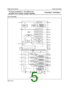
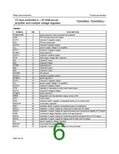
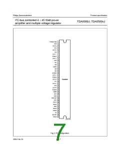
I2C-bus controlled 4 45 Watt power
amplier and multiple voltage regulator
TDA8589J; TDA8589xJ
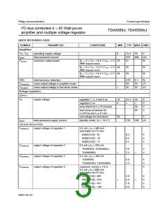
QUICK REFERENCE DATA
SYMBOL
PARAMETER
CONDITIONS
MIN. TYP. MAX. UNIT
Ampliers
VP1, VP2
Iq(tot)
operating supply voltage
total quiescent current
maximum output power
8
14.4
270
41
18
V
400
mA
W
Po(max)
RL = 4 ; VP = 14.4 V; VIN = 2 V 39
RMS square wave
RL = 4 ; VP = 15.2 V; VIN = 2 V 44
RMS square wave
46
69
W
W
RL = 2 ; VP = 14.4 V; VIN = 2 V 64
RMS square wave
THD
total harmonic distortion
0.01
50
0.1
70
35
%
V
Vn(o)(amp)
Vn(o)(LN)
noise output voltage in amplier mode
noise output voltage in line driver mode
25
V
Voltage regulators
SUPPLY
VP
supply voltage
regulator 1, 3, 4 and 5 on
regulator 2 on
10
4
14.4
150
18
V
V
V
V
jump starts for t 10 minutes
30
50
load dump protection for
t
50 ms and tr 2.5 ms
overvoltage for shut-down
standby mode; VP = 14.4 V
20
V
A
Iq(tot)
total quiescent supply current
190
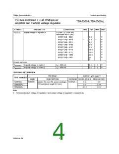
VOLTAGE REGULATORS
VO(REG1)
output voltage of regulator 1
0.5 mA IO 400 mA;
selectable via I2C-bus
IB2[D3:D2] = 01
IB2[D3:D2] = 10
8.3
8.5
8.7
V
V
V
IB2[D3:D2] = 11
VO(REG2)
VO(REG3)
VO(REG4)
output voltage of regulator 2
output voltage of regulator 3
output voltage of regulator 4
0.5 mA IO 350 mA
TDA8589J; TDA8589AJ
TDA8589BJ
5.0
3.3
V
V
0.5 mA IO 300 mA
TDA8589J
5.0
3.3
V
V
V
TDA8589AJ; TDA8589BJ
maximum current 1.6 A;
0.5 mA IO 800 mA;
selectable via I2C-bus
IB2[D7:D5] = 001
IB2[D7:D5] = 010
IB2[D7:D5] = 011
IB2[D7:D5] = 100
5.0
6.0
7.0
8.6
V
V
V
V
2004 Feb 24
3

 NXP [ NXP ]