LPC546xx
NXP Semiconductors
32-bit ARM Cortex-M4 microcontroller
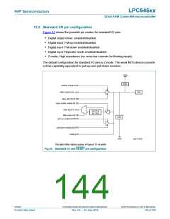
13.2 Standard I/O pin configuration
Figure 44 shows the possible pin modes for standard I/O pins:
• Digital output driver: enabled/disabled.
• Digital input: Pull-up enabled/disabled.
• Digital input: Pull-down enabled/disabled.
• Digital input: Repeater mode enabled/disabled.
• Z mode; High impedance (no cross-bar currents for floating inputs).
The default configuration for standard I/O pins is Z mode. The weak MOS devices provide
a drive capability equivalent to pull-up and pull-down resistors.
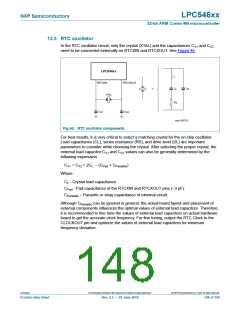
VDD
ESD
enable output driver
data output from core
PIN
slew rate bit SLEW
input buffer enable bit EZI
data input to core
GLITCH
FILTER
filter select bit ZIF
ESD
VSS
pull-up enable bit EPUN
pull-down enable bit EPD
analog I/O
aaa-015595
The glitch filter rejects pulses of typical 12 ns width.
Fig 44. Standard I/O and RESET pin configuration
LPC546xx
All information provided in this document is subject to legal disclaimers.
© NXP Semiconductors N.V. 2018. All rights reserved.
Product data sheet
Rev. 2.5 — 20 June 2018
144 of 169

 NXP [ NXP ]