Device operations
NAND01G-B2B, NAND02G-B2C
6.3
Page program
The page program operation is the standard operation to program data to the memory array.
Generally, the page is programmed sequentially, however the device does support random
input within a page. It is recommended to address pages sequentially within a given block.
The memory array is programmed by page, however partial page programming is allowed
where any number of bytes (1 to 2112) or words (1 to 1056) can be programmed.
The maximum number of consecutive partial page program operations allowed in the same
page is four. After exceeding this a Block Erase command must be issued before any further
program operations can take place in that page.
6.3.1
Sequential input
To input data sequentially the addresses must be sequential and remain in one block.
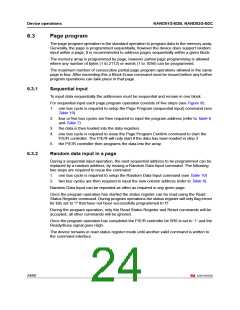
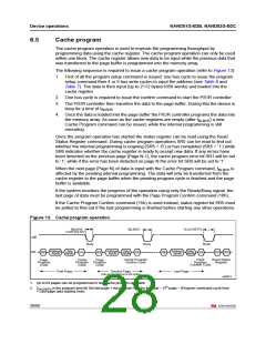
For sequential input each page program operation consists of five steps (see Figure 9):
1. one bus cycle is required to setup the Page Program (sequential input) command (see
Table 10)
2. four or five bus cycles are then required to input the program address (refer to Table 6
and Table 7)
3. the data is then loaded into the data registers
4. one bus cycle is required to issue the Page Program Confirm command to start the
P/E/R controller. The P/E/R will only start if the data has been loaded in step 3
5. the P/E/R controller then programs the data into the array.
6.3.2
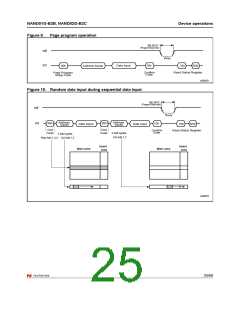
Random data input in a page
During a sequential input operation, the next sequential address to be programmed can be
replaced by a random address, by issuing a Random Data Input command. The following
two steps are required to issue the command:
1. one bus cycle is required to setup the Random Data Input command (see Table 10)
2. two bus cycles are then required to input the new column address (refer to Table 6).
Random Data Input can be repeated as often as required in any given page.
Once the program operation has started the status register can be read using the Read
Status Register command. During program operations the status register will only flag errors
for bits set to '1' that have not been successfully programmed to '0'.
During the program operation, only the Read Status Register and Reset commands will be
accepted, all other commands will be ignored.
Once the program operation has completed the P/E/R controller bit SR6 is set to ‘1’ and the
Ready/Busy signal goes High.
The device remains in read status register mode until another valid command is written to
the command interface.
24/60

 NUMONYX [ NUMONYX B.V ]