NAND01G-B2B, NAND02G-B2C
Device operations
6.2
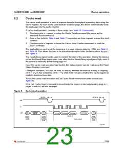
Cache read
The cache read operation is used to improve the read throughput by reading data using the
cache register. As soon as the user starts to read one page, the device automatically loads
the next page into the cache register.
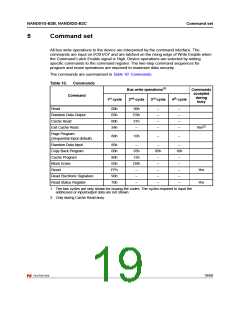
A cache read operation consists of three steps (see Table 10: Commands):
1. One bus cycle is required to setup the Cache Read command (the same as the
standard Read command)
2. Four or five (refer to Table 6 and Table 7) bus cycles are then required to input the start
address
3. One bus cycle is required to issue the Cache Read Confirm command to start the
P/E/R controller.
The start address must be at the beginning of a page (column address = 00h, see Table 8
and Table 9). This allows the data to be output uninterrupted after the latency time (t
see Figure 8.
),
BLBH1
The Ready/Busy signal can be used to monitor the start of the operation. During the latency
period the Ready/Busy signal goes Low, after this the Ready/Busy signal goes High, even if
the device is internally downloading page n+1.
Once the cache read operation has started, the status register can be read using the Read
Status Register command.
During the operation, SR5 can be read, to find out whether the internal reading is ongoing
(SR5 = ‘0’), or has completed (SR5 = ‘1’), while SR6 indicates whether the cache register is
ready to download new data.
To exit the cache read operation an Exit Cache Read command must be issued (see
Table 10).
If the Exit Cache Read command is issued while the device is internally reading page n+1,
pages n and n+1 will not be output.
Figure 8.
Cache read operation
tBLBH1
tBLBH4
(Read Busy time)
RB
R
Busy
Address
inputs
last page
34h
I/O
31h
00h
1st page
2nd page 3rd page
Block N
Exit
Cache
Read
code
Read
Setup
code
Cache
Read
Confirm
code
Data output
ai13104b
23/60

 NUMONYX [ NUMONYX B.V ]