Command interface state tables
M58LT256JST, M58LT256JSB
(1) (2)
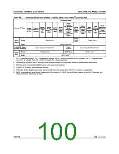
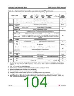
Table 48. Command interface states - lock table, next output state (continued)
Command Input
Block
Current CI State
Protect/CR
Blank
Setup (6 Checksetup Setup
0h) (BCh) (C0h)
OTP
BlankCheck
confirm
Set CR BEFP
Confirm Exit
(03h) (FFFFh)
Illegal
P. E./C.
Protect
Confirm
(01h)
(3)
(3)
(4)
Command Operation
(5)
(CBh)
Completed
OTP Busy
Ready
Program Busy
Erase Busy
Buffer Program Busy
Program/Erase Suspend
Buffer Program Suspend
Program Busy in Erase Suspend
Status Register
Output Unchanged
Array
Output Unchanged
Buffer Program Busy in Erase
Suspend
Program Suspend in Erase Suspend
Buffer Program Suspend in Erase
Suspend
Blank Check busy
Illegal State
Output Unchanged
1. The output state shows the type of data that appears at the outputs if the bank address is the same as the command
address. A bank can be placed in Read Array, Read Status Register, Read Electronic Signature or Read CFI mode,
depending on the command issued. Each bank remains in its last output state until a new command is issued to that bank.
The next state does not depend on the bank's output state.
2. CI = Command Interface, CR = Configuration Register, BEFP = Buffer Enhanced Factory Program, P/E. C. =
Program/Erase Controller.
3. If the P/EC is active, both cycles are ignored.
4. BEFP Exit when Block Address is different from first Block Address and data are FFFFh.
5. Illegal commands are those not defined in the command set.
106/108

 NUMONYX [ NUMONYX B.V ]