®
Numonyx™ StrataFlash Embedded Memory (J3-65nm)
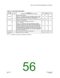
Table 37: Burst Read Information
(1)
Offset
Description
(Optional Flash Features and Commands)
Hex
Code
Length
Add.
Value
P = 31h
Page Mode Read capability
bits 0–7 = “n” such that 2n HEX value represents the number of read-
page bytes. See offset 28h for device word width to determine page-
mode data output width. 00h indicates no read page buffer.
(P+13)h
1
1
44:
45:
--05
--00
32 bytes
0
Number of synchronous mode read configuration fields that follow. 00h
indicates no burst capability.
(P+14)h
Synchronous Mode Read Capability Configuration 1
Bits 3-7 = Reserved
n+1
bits 0-2 = “n” such that 2
HEX value represents the maximum
number of continuous synchronous burst reads when the device is
configured for its maximum word width. A value of 07h indicates that
the device is capable of continuous linear bursts until that will output
data until the internal burst counter reaches the end of the device’s
burstable address space. This field’s 3-bit value can be written directly
to the Read Configuration Register Bits 0-2 if the device is configured for
its maximum word width. See offset 1Fh for word width to determine
the burst data output width.
(P+15)h
1
46:
--00
n/a
(P+16h)h
(P+45h)h
Note:
1
1
Synchronous Mode Read Capability Configuration 2
J3C mark for VIL fix for customers
47:
76:
--00
--01
n/a
01
1.
The variable P is a pointer which is defined at CFI offset 15h.
Datasheet
56
December 2008
319942-02

 NUMONYX [ NUMONYX B.V ]