Application Information (Continued)
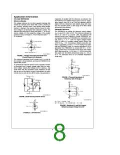
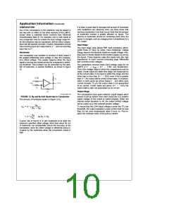
Understanding that V is fixed and that voltage sources, re-
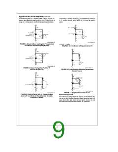
Connecting a resistor across V -to-FEEDBACK creates a
RO
0 TC current source, but a range of TCs may be synthe-
sized.
r
sistors, and capacitors may be tied to the FEEDBACK pin, a
range of V temperature coefficients may be synthesized.
r
TL/H/11057–14
FIGURE 6. Output Voltage has Negative Temperature
Coefficient (TC) if R2 has Negative TC
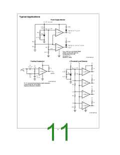
TL/H/11057–17
e
e
1.24/R1
I
V /R1
r
FIGURE 9. Current Source is Programmed by R1
TL/H/11057–15
FIGURE 7. Output Voltage has Positive TC
if R1 has Negative TC
TL/H/11057–18
FIGURE 10. Proportional-to-Absolute-Temperature
Current Source
TL/H/11057–19
TL/H/11057–16
FIGURE 8. Diode in Series with R1 Causes Voltage
Across R1 and R2 to be Proportional to Absolute
Temperature (PTAT)
FIGURE 11. Negative-TC Current Source
Reference Hysteresis
The reference voltage depends, slightly, on the thermal his-
tory of the die. Competitive micro-power products varyÐal-
ways check the data sheet for any given device. Do not
assume that no specification means no hysteresis.
9

 NSC [ National Semiconductor ]