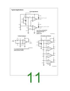
Application Information
VOLTAGE REFERENCE
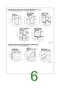
Capacitors in parallel with the reference are allowed. See
the Reference AC Stability Range typical curve for capaci-
tance valuesÐfrom 20 mA to 3 mA any capacitor value is
stable. With the reference’s wide stability range with resis-
tive and capacitive loads, a wide range of RC filter values
will perform noise filtering.
Reference Biasing
The voltage reference is of a shunt regulator topology that
models as a simple zener diode. With current I flowing in
r
the ‘‘forward’’ direction there is the familiar diode transfer
function. I flowing in the reverse direction forces the refer-
r
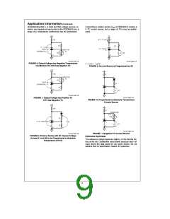
Adjustable Reference
ence voltage to be developed from cathode to anode. The
cathode may swing from a diode drop below Vb to the ref-
erence voltage or to the avalanche voltage of the parallel
The FEEDBACK pin allows the reference output voltage,
, to vary from 1.24V to 6.3V. The reference attempts to
V
ro
hold V at 1.24V. If V is above 1.24V, the reference will
protection diode, nominally 7V. A 6.3V reference with Va
e
r
r
3V is allowed.
conduct current from Cathode to Anode; FEEDBACK cur-
rent always remains low. If FEEDBACK is connected to An-
e
e
BACK is held at a constant voltage above AnodeÐsay
ode, then V
V
r
1.24V. For higher voltages FEED-
ro
e
3.76V for V
5V. Connecting a resistor across the con-
ro
stant V generates a current I
ode into FEEDBACK node. A Thevenin equivalent 3.76V is
e
R1/V flowing from Cath-
r
r
e
Keep I greater than one thousand times larger than FEED-
generated from FEEDBACK to Anode with R2
3.76/I.
k
t
BACK bias current for 0.1% errorÐI 32 mA for the mili-
t
tary grade over the military temperature range (I
5.5 mA
TL/H/11057–9
for a 1% untrimmed error for an industrial temperature
range part).
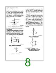
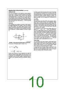
FIGURE 1. Voltage Associated with Reference
(Current Source I is External)
r
The reference equivalent circuit reveals how V is held at
r
the constant 1.2V by feedback, and how the FEEDBACK pin
passes little current.
To generate the required reverse current, typically a resistor
is connected from a supply voltage higher than the refer-
ence voltage. Varying that voltage, and so varying I , has
r
small effect with the equivalent series resistance of less
than an ohm at the higher currents. Alternatively, an active
current source, such as the LM134 series, may generate I .
r
TL/H/11057–12
FIGURE 4. Thevenin Equivalent of
Reference with 5V Output
TL/H/11057–10
FIGURE 2. Reference Equivalent Circuit
TL/H/11057–13
e
e
e
e
1.24/32m 39k
R1
R2
V /I
r
[
b
e
b
e
]
1 118k
]
[
39k (5/1.24)
R1 (V /V )
ro
1
r
FIGURE 5. Resistors R1 and R2 Program
Reference Output Voltage to be 5V
TL/H/11057–11
FIGURE 3. 1.2V Reference
8

 NSC [ National Semiconductor ]