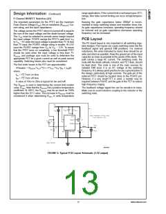
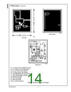
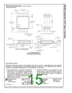
Design Information
Hysteretic control is a simple control scheme. However the
operating frequency and other performance characteristics
highly depend on external conditions and components. If
either the inductance, output capacitance, ESR, VIN, or Cff is
changed, there will be a change in the operating frequency
and output ripple. The best approach is to determine what
operating frequency is desirable in the application and then
begin with the selection of the inductor and COUT ESR.
OS-CON, Panasonic SP CAP, Nichicon ’NA’ series, are also
recommended and may be used without additional series
resistance.
For all practical purposes, any type of output capacitor may
be used with proper circuit verification.
Input Capacitor Selection (CIN
)
A bypass capacitor is required between the input source and
ground. It must be located near the source pin of the external
PFET. The input capacitor prevents large voltage transients
at the input and provides the instantaneous current when the
PFET turns on.
Inductor Selection (L1)
The important parameters for the inductor are the induc-
tance and the current rating. The LM3485 operates over a
wide frequency range and can use a wide range of induc-
tance values. A good rule of thumb is to use the equations
used for National’s Simple Switchers®. The equation for
inductor ripple (∆i) as a function of output current (IOUT) is:
The important parameters for the input capacitor are the
voltage rating and the RMS current rating. Follow the manu-
facturer’s recommended voltage derating. For high input
voltage application, low ESR electrolytic capacitor, the Nichi-
con ’UD’ series or the Panasonic ’FK’ series, is available.
The RMS current in the input capacitor can be calculated.
<
for Iout 2.0Amps
−0.366726
*
*
∆i ≤ Iout 0.386827 Iout
>
for Iout 2.0Amps
*
∆i ≤ Iout 0.3
The inductance can be calculated based upon the desired
operating frequency where:
The input capacitor power dissipation can be calculated as
follows.
2
*
PD(CIN) = IRMS_CIN
ESRCIN
The input capacitor must be able to handle the RMS current
and the PD. Several input capacitors may be connected in
parallel to handle large RMS currents. In some cases it may
be much cheaper to use multiple electrolytic capacitors than
a single low ESR, high performance capacitor such as
OS-CON or Tantalum. The capacitance value should be
selected such that the ripple voltage created by the charge
and discharge of the capacitance is less than 10% of the
total ripple across the capacitor.
And
where D is the duty cycle and VD is the diode forward
voltage.
The inductor should be rated to the following:
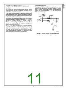
Programming the Current Limit (RADJ
)
*
Ipk = (Iout+∆i/2) 1.1
The current limit is determined by connecting a resistor
(RADJ) between input voltage and the ADJ pin.
*
RADJ = IIND_PEAK RDSON/ICL_ADJ
where:
DSON : Drain-Source ON resistance of the external PFET
The inductance value and the resulting ripple is one of the
key parameters controlling operating frequency. The second
is the ESR.
R
ICL_ADJ : 5.5µA typically
IIND_PEAK = ILOAD + IRIPPLE/2
Output Capacitor Selection (COUT
)
Catch Diode Selection (D1)
The ESR of the output capacitor times the inductor ripple
current is equal to the output ripple of the regulator. How-
ever, the VHYST sets the first order value of this ripple. As
ESR is increased with a given inductance, then operating
frequency increases as well. If ESR is reduced then the
operating frequency reduces.
The important parameters for the catch diode are the peak
current, the peak reverse voltage, and the average power
dissipation. The average current through the diode can be
calculated as following.
*
ID_AVE = IOUT (1 − D)
The off state voltage across the catch diode is approximately
equal to the input voltage. The peak reverse voltage rating
must be greater than input voltage. In nearly all cases a
shottky diode is recommended. In low output voltage appli-
cations a low forward voltage provides improved efficiency.
For high temperature applications, diode leakage current
may become significant and require a higher reverse voltage
rating to achieve acceptable performance.
The use of ceramic capacitors has become a common de-
sire of many power supply designers. However, ceramic
capacitors have a very low ESR resulting in a 90˚ phase shift
of the output voltage ripple. This results in low operating
frequency and increased output ripple. To fix this problem a
low value resistor should be added in series with the ceramic
output capacitor. Although counter intuitive, this combination
of a ceramic capacitor and external series resistance provide
highly accurate control over the output voltage ripple. The
other types capacitor, such as Sanyo POS CAP and
www.national.com
12

 NSC [ National Semiconductor ]