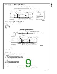
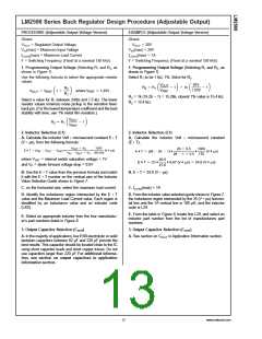
Test Circuit and Layout Guidelines
Fixed Output Voltage Versions
DS012593-23
Component Values shown are for V = 15V, V
= 5V, I
= 1A.
LOAD
IN
OUT
120 µF, 50V, Aluminum Electrolytic Nichicon “PL Series”
120 µF, 35V Aluminum Electrolytic, Nichicon “PL Series”
3A, 40V Schottky Rectifier, 1N5822
68 µH, L30
Typical Values
*C
:
— 0.1 µF
— 0.1 µF
— 4.7k
SS
C
R
:
:
DELAY
Pull Up
Adjustable Output Voltage Versions
DS012593-24
where V
= 1.23V
REF
Select R to be approximately 1kΩ, use a 1% resistor for best stability.
1
Component Values shown are for V = 20V,
IN
V
OUT
= 10V, I
= 1A.
LOAD
C
C
— 120 µF, 35V, Aluminum Electrolytic Nichicon “PL Series”
— 120 µF, 35V Aluminum Electrolytic, Nichicon “PL Series”
IN
OUT
D1 — 3A, 40V Schottky Rectifier, 1N5822
L1 — 100 µH, L29
R
R
C
R
— 1 kΩ, 1%
— 7.15k, 1%
— 3.3 nF, See Application Information Section
— 3 kΩ, See Application Information Section
1
2
FF
FF
Typical Values
C
C
R
— 0.1 µF
SS
— 0.1 µF
DELAY
— 4.7k
PULL UP
FIGURE 1. Standard Test Circuits and Layout Guides
9
www.national.com

 NSC [ National Semiconductor ]