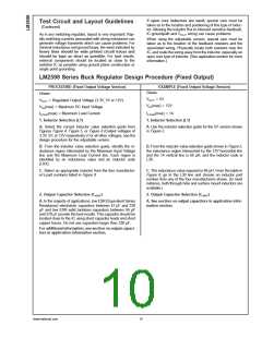
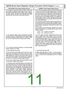
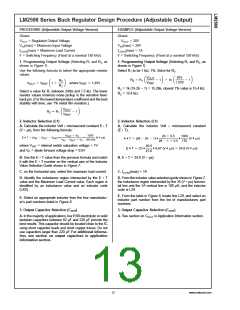
LM2598 Series Buck Regulator Design Procedure (Adjustable Output)
(Continued)
PROCEDURE (Adjustable Output Voltage Version)
EXAMPLE (Adjustable Output Voltage Version)
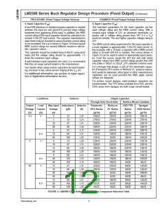
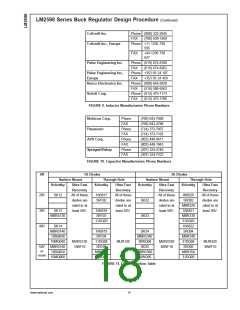
B. To simplify the capacitor selection procedure, refer to the
quick design table shown in Figure 3. This table contains
different output voltages, and lists various output capacitors
that will provide the best design solutions.
B. From the quick design table shown in Figure 3, locate the
output voltage column. From that column, locate the output
voltage closest to the output voltage in your application. In
this example, select the 24V line. Under the output capacitor
section, select a capacitor from the list of through hole elec-
trolytic or surface mount tantalum types from four different
capacitor manufacturers. It is recommended that both the
manufacturers and the manufacturers series that are listed in
the table be used.
In this example, through hole aluminum electrolytic capaci-
tors from several different manufacturers are available.
82 µF 35V Panasonic HFQ Series
82 µF 35V Nichicon PL Series
C. The capacitor voltage rating should be at least 1.5 times
greater than the output voltage, and often much higher volt-
age ratings are needed to satisfy the low ESR requirements
needed for low output ripple voltage.
C. For a 20V output, a capacitor rating of at least 30V or
more is needed. In this example, either a 35V or 50V capaci-
tor would work. A 35V rating was chosen although a 50V
rating could also be used if a lower output ripple voltage is
needed.
Other manufacturers or other types of capacitors may also
be used, provided the capacitor specifications (especially the
100 kHz ESR) closely match the types listed in the table.
Refer to the capacitor manufacturers data sheet for this
information.
4. Feedforward Capacitor (CFF) (See Figure 1)
4. Feedforward Capacitor (CFF)
For output voltages greater than approximately 10V, an ad-
ditional capacitor is required. The compensation capacitor is
typically between 50 pF and 10 nF, and is wired in parallel
with the output voltage setting resistor, R2. It provides addi-
tional stability for high output voltages, low input-output volt-
ages, and/or very low ESR output capacitors, such as solid
tantalum capacitors.
The table shown in Figure 3 contains feed forward capacitor
values for various output voltages. In this example, a 1 nF
capacitor is needed.
This capacitor type can be ceramic, plastic, silver mica, etc.
(Because of the unstable characteristics of ceramic capaci-
tors made with Z5U material, they are not recommended.)
5. Catch Diode Selection (D1)
5. Catch Diode Selection (D1)
A. The catch diode current rating must be at least 1.3 times
greater than the maximum load current. Also, if the power
supply design must withstand a continuous output short, the
diode should have a current rating equal to the maximum
current limit of the LM2598. The most stressful condition for
this diode is an overload or shorted output condition.
A. Refer to the table shown in Figure 11. Schottky diodes
provide the best performance, and in this example a 3A, 40V,
1N5822 Schottky diode would be a good choice. The 3A
diode rating is more than adequate and will not be over-
stressed even for a shorted output.
B. The reverse voltage rating of the diode should be at least
1.25 times the maximum input voltage.
C. This diode must be fast (short reverse recovery time) and
must be located close to the LM2598 using short leads and
short printed circuit traces. Because of their fast switching
speed and low forward voltage drop, Schottky diodes provide
the best performance and efficiency, and should be the first
choice, especially in low output voltage applications.
Ultra-fast recovery, or High-Efficiency rectifiers are also a
good choice, but some types with an abrupt turn-off charac-
teristic may cause instability or EMl problems. Ultra-fast re-
covery diodes typically have reverse recovery times of 50 ns
or less. Rectifiers such as the 1N4001 series are much too
slow and should not be used.
www.national.com
14

 NSC [ National Semiconductor ]