LM2598 Series Buck Regulator Design Procedure (Adjustable Output)
(Continued)
PROCEDURE (Adjustable Output Voltage Version)
EXAMPLE (Adjustable Output Voltage Version)
6. Input Capacitor (CIN
)
6. Input Capacitor (CIN)
A low ESR aluminum or tantalum bypass capacitor is needed
between the input pin and ground to prevent large voltage
transients from appearing at the input. In addition, the RMS
current rating of the input capacitor should be selected to be
The important parameters for the Input capacitor are the
input voltage rating and the RMS current rating. With a
nominal input voltage of 28V, an aluminum electrolytic alumi-
num electrolytic capacitor with a voltage rating greater than
42V (1.5 x VIN) would be needed. Since the the next higher
capacitor voltage rating is 50V, a 50V capacitor should be
used. The capacitor voltage rating of (1.5 x VIN) is a conser-
vative guideline, and can be modified somewhat if desired.
at least 1⁄
the DC load current. The capacitor manufacturers
2
data sheet must be checked to assure that this current rating
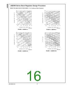
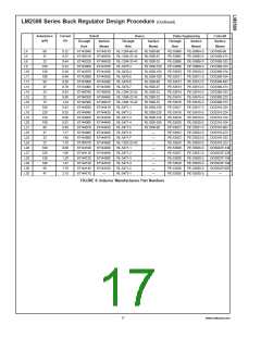
is not exceeded. The curve shown in Figure 16 shows typical
RMS current ratings for several different aluminum electro-
lytic capacitor values.
The RMS current rating requirement for the input capacitor of
1
This capacitor should be located close to the IC using short
leads and the voltage rating should be approximately 1.5
times the maximum input voltage.
a buck regulator is approximately ⁄
2
the DC load current. In
this example, with a 1A load, a capacitor with a RMS current
rating of at least 500 mA is needed.
If solid tantalum input capacitors are used, it is recomended
that they be surge current tested by the manufacturer.
The curves shown in Figure 16 can be used to select an
appropriate input capacitor. From the curves, locate the 50V
line and note which capacitor values have RMS current
ratings greater than 500 mA. Either a 100 µF or 120 µF, 50V
capacitor could be used.
Use caution when using a high dielectric constant ceramic
capacitor for input bypassing, because it may cause severe
ringing at the VIN pin.
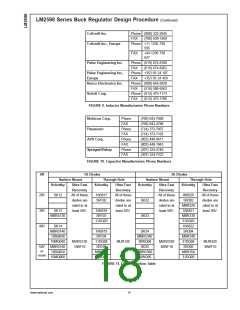
For a through hole design, a 120 µF/50V electrolytic capaci-
tor (Panasonic HFQ series or Nichicon PL series or equiva-
lent) would be adequate. Other types or other manufacturers
capacitors can be used provided the RMS ripple current
ratings are adequate.
For surface mount designs, solid tantalum capacitors can be
used, but caution must be exercised with regard to the
capacitor surge current rating (see Application Information or
input capacitors in this data sheet). The TPS series available
from AVX, and the 593D series from Sprague are both surge
current tested.
For additional information, see section on input capaci-
tor in application information section.
To further simplify the buck regulator design procedure, Na-
tional Semiconductor is making available computer design
software to be used with the Simple Switcher line ot switch-
ing regulators. Switchers Made Simple (version 4.2 or later)
is available on a 31⁄
" diskette for IBM compatible computers.
2
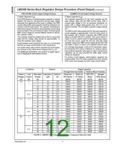
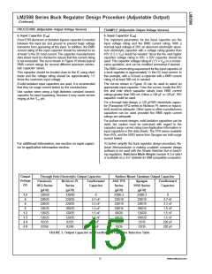
Output
Voltage
(V)
Through Hole Electrolytic Output Capacitor
Surface Mount Tantalum Output Capacitor
Panasonic
HFQ Series
(µF/V)
Nichicon PL
Series
(µF/V)
Feedforward
Capacitor
AVX TPS
Series
(µF/V)
330/6.3
220/10
220/10
100/16
68/20
Sprague
595D Series
(µF/V)
Feedforward
Capacitor
1.2
4
330/50
220/25
220/25
180/25
120/25
120/25
82/35
330/50
220/25
220/25
180/25
120/25
120/25
82/35
0
330/6.3
220/10
0
4.7 nF
3.3 nF
1.5 nF
1.5 nF
1.5 nF
1 nF
4.7 nF
3.3 nF
1.5 nF
1.5 nF
1.5 nF
220 pF
220 pF
6
220/10
9
180/16
1 2
1 5
2 4
2 8
120/20
68/20
100/20
33/25
33/35
82/50
82/50
1 nF
10/35
33/35
FIGURE 3. Output Capacitor and Feedforward Capacitor Selection Table
15
www.national.com

 NSC [ National Semiconductor ]